Pressure Direction
Positive-pressure supply and negative-pressure extraction impose different structural demands. The wrong format can lead to collapse, excessive movement or poor airflow.



 Underground Airflow Systems
Project-configured flexible ducting for fresh-air supply, contaminated-air extraction and temporary underground ventilation—specified by pressure direction, fan duty, route geometry and connection method.
DERFLEX supplies finished mine ventilation duct sections and PVC-coated ducting materials for mines, tunnels, shafts and underground construction. Performance options are confirmed against the project specification and applicable test method before production.
Mine ventilation ducting forms the temporary or semi-permanent air path between an auxiliary fan and an underground working area. The duct may deliver fresh air toward a heading, draw dust or fumes away from an equipment zone, or connect a changing route where rigid duct would be slow to extend and difficult to store.
The correct construction depends first on airflow direction. A collapsible layflat tube is commonly used for forced-air supply because internal pressure inflates the duct. Suction or exhaust duty generally requires rings or a continuous wire helix so the duct does not collapse under negative pressure. Where headroom is limited, an oval or twin-chamber arrangement can reduce the occupied vertical space.
DERFLEX combines PVC-coated technical textile, welded fabrication, reinforcement and project-defined fittings into finished mine air duct sections. This makes it possible to coordinate the fabric body, seam, suspension, coupling and route details as one purchasing package instead of treating each component separately.
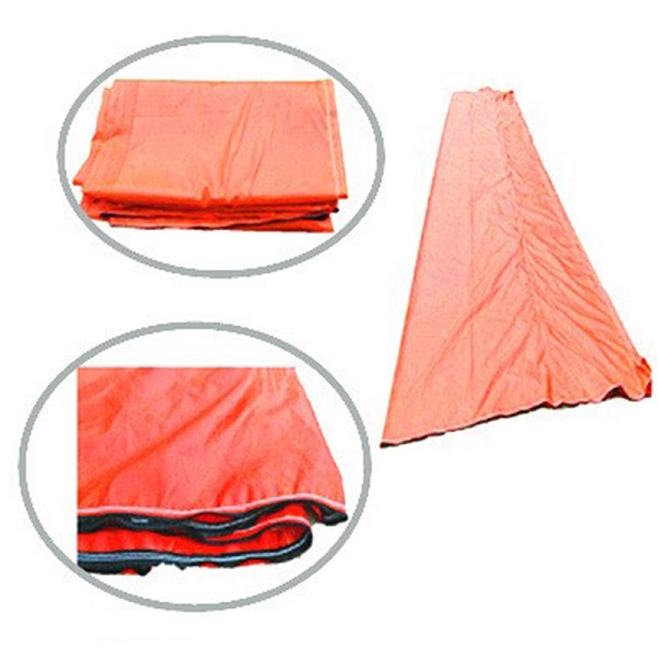
Airflow efficiency and service life are influenced by the complete duct system, not by fabric weight alone.
Positive-pressure supply and negative-pressure extraction impose different structural demands. The wrong format can lead to collapse, excessive movement or poor airflow.
Weld quality, end cuffs and coupling selection influence how much fan output reaches the active heading over a long duct run.
Diameter, bends, elevation changes, low-clearance passages and moving work fronts affect the recommended duct type and accessory layout.
Rock contact, handling and repeated relocation can concentrate wear at the underside, suspension points, couplings and bends.
Flame-retardant and antistatic options should be matched to the required project standard, test method and operating environment.
Section length, packaging, suspension spacing and connection speed matter when the air line must advance with the mine or tunnel face.
Each product can be configured by diameter, length, coupling, suspension and treatment requirements.
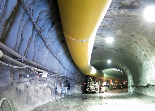
Collapsible air-forcing sections for carrying fresh air along mine headings and advancing tunnel routes. Compact when packed and inflated by the fan during operation.
View layflat positive-pressure duct →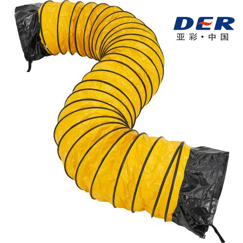
A continuous helix helps the duct retain shape under negative pressure, through bends and at equipment connections. Wear strips and reinforced cuffs are available.
View spiral wire-reinforced duct →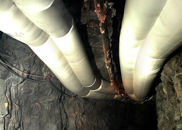
Alternative profiles can be considered where round ducting interferes with vehicles, services or roof clearance. The layout should be reviewed with the available opening and required airflow.
Compare low-headroom selection factors →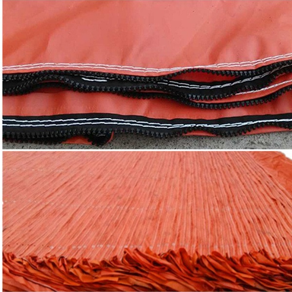
Reducers, branch pieces, end cuffs, zippers, rings, clamps, suspension points and wear reinforcements can be coordinated around the route and installation method.
Review custom duct accessories →DERFLEX can supply coated material or completed duct sections, allowing the product structure to be selected around the intended fabrication and field use.
Industrial filament fabric provides the load-bearing structure, while the PVC coating supports air containment, moisture resistance and weldable fabrication.
Hot-air or high-frequency welding can create continuous seams selected for the fabric construction and duct geometry.
Suspension points, end cuffs, zipper areas and contact zones can receive extra layers or wear strips where repeated loading is expected.
Flame-retardant, antistatic, cold-weather, high-visibility or abrasion-oriented formulations can be discussed against a defined test requirement.
The final layer arrangement varies with the selected material, pressure duty and reinforcement system.
The values below describe common project options. Final selections depend on pressure calculations, route layout, required tests and production confirmation.
| Specification Item | Typical Project Options | Selection Considerations |
|---|---|---|
| Product Form | Finished layflat duct, ring-supported duct, spiral-wire duct, oval/twin duct or coated fabric roll | Choose by positive or negative pressure and required field assembly |
| Duct Body Material | PVC-coated polyester technical textile; project-selected weight and yarn construction | Pressure, abrasion, handling frequency, flame/antistatic requirement and service life |
| Diameter | Approximately 300–3000 mm; custom sizes subject to engineering review | Required airflow, available headroom, fan curve and route losses |
| Section Length | 5–100 m common fabrication range; longer sections can be discussed | Installation rhythm, handling weight, storage and coupling frequency |
| Reinforcement | None, periodic rings, continuous steel-wire helix, reinforced wear strip | Pressure direction, bends, suction duty and contact exposure |
| Connections | Zipper, hook-and-loop, steel ring, clamp, eyelet, sleeve or drawing-based interface | Leakage target, installation speed, compatibility and maintenance access |
| Suspension | D-rings, eyelets, reinforced fin, cable clips or custom hanger spacing | Duct weight, route curvature, ceiling condition and dynamic movement |
| Performance Options | Flame-retardant, antistatic, cold-resistant, high-visibility, abrasion-oriented and custom color | Must be linked to a written project requirement and agreed test method |
| Pressure Capability | Defined by completed duct construction rather than fabric weight alone | Confirm fan duty, diameter, seam, reinforcement, coupling and section length |
| Inspection Documents | Dimensional, material and agreed performance records available by order requirement | Specify documentation and third-party testing needs before quotation |
Engineering note: fan power or static pressure alone is not sufficient to select a duct. The quotation should consider airflow volume, total run length, diameter, bend count, elevation, leakage allowance, connection style and local project requirements.
Use this comparison as a purchasing starting point, then confirm the completed duct design against the fan and route.
Designed primarily for positive-pressure air supply.
Selected where the duct must resist collapse or route through bends.
Considered where vertical clearance is restricted.
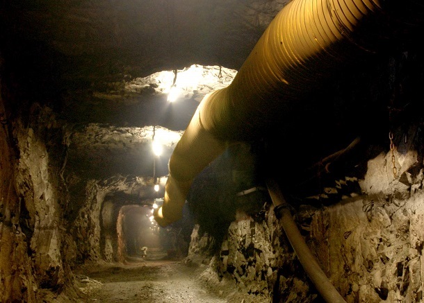
Flexible systems are especially useful where ventilation routes move, clearances vary or rapid installation is important.
Inspection points can be aligned with the purchased product form and agreed project documentation.
Airflow direction, fan data, run length, route, diameter, safety options and coupling interface are clarified.
Base fabric, coating, weight, surface treatment and reinforcement are selected for the intended duty.
Panels, seams, cuffs, suspension zones, zippers, rings and wear patches are fabricated to confirmed dimensions.
Dimensions, visual seam quality, connection details and agreed tests are checked according to the order plan.
Sections can be labeled by diameter, length, route or installation sequence to simplify site identification.
A more complete project brief allows the quotation to address the system rather than only a unit price per meter.
These pages cover adjacent product formats, construction details and application options.
Answers are provided as general selection guidance; final performance should be confirmed for the completed duct and project requirement.
Positive-pressure ducting is inflated by air pushed from the fan and is commonly supplied as a collapsible layflat tube. Negative-pressure ducting must resist collapse while air is extracted, so it normally uses steel rings or a continuous wire helix. A project using both airflow modes may require different duct constructions in different parts of the system.
Diameter should be selected from the required airflow, air velocity, pressure loss, fan curve, route length, bend count and available clearance. A larger diameter may reduce friction loss but requires more installation space. DERFLEX recommends reviewing these inputs together rather than selecting diameter from fan power alone.
Yes. DERFLEX can quote fabricated duct sections with welded seams, end cuffs, suspension points, coupling details and optional reinforcement. PVC-coated ducting fabric can also be supplied for customers that fabricate locally.
These options can be discussed for defined project requirements. The required standard, test method, acceptance value and documentation should be identified before production because terminology and thresholds vary by market and mine type.
Leakage control depends on seam construction, coupling overlap, zipper or ring design, section alignment and installation practice. Fewer connections may reduce potential leakage points, while shorter sections can be easier to handle and replace. The preferred balance should be set by the route and maintenance plan.
Please provide airflow direction, fan data, required airflow, duct diameter, total route length, section length, bends or branches, coupling preference, suspension method, operating environment and any specified flame, antistatic, cold-weather, color, labeling or inspection requirements.
Send the fan data, route length, diameter, airflow mode, connection preference and project performance requirements. The DERFLEX team will review suitable material and fabrication options for your mine ventilation ducting program.
Fan curve or model, route sketch, installation photos, existing duct sample, connection drawing, required test specification and expected order quantity.