Freeze the covered configuration.
Record the equipment drawing identifier and revision, reference photos, measurement units, fitted accessories and the parts included inside the cover boundary.




Equipment protection / Design & fit approval
A fitted equipment cover starts with the machine’s geometry, attachment points and access needs. Follow the development workflow from measured views and controlled drawings to cut panels, reinforcement, first-article fitting and revision release.
DERFLEX supports PVC coated fabric, cut panels and finished custom covers. Define the required supply scope and validate the fit on the actual equipment before releasing a repeat order.
Start with an equipment outline, marked anchor points and opening requirements. Attach photos or drawings in your email to sales@derflex.com.
The approval principle
Approve a custom machinery tarp when the identified first article fits the specified equipment configuration, its openings and fasteners function as agreed, and every required change is reflected in the released drawing.
Length, width and height establish the overall envelope. They do not locate a control box, define the route around a fixed pipe, or prove that a strap can reach an anchor without rubbing a cable. The useful approval record connects each equipment interface to a drawing detail, a constructed feature and an observed fit check.
For the broader supply options, see custom machinery covers for OEM and industrial equipment. This workflow focuses on the decisions that turn an equipment outline into a repeatable fitted cover.
Measurement / Equipment configuration
Identify the equipment model and the condition in which it will be covered: stored, packed for shipment or parked between uses. Show whether handles are folded, hoses are connected, wheels are fitted and removable accessories are installed.
Measure the equipment first. Show any proposed fitting clearance separately; a cover supplier should not have to guess whether the submitted dimensions already include extra allowance.
Schematic / Measurement references only / Not to scale
Drawing / Scope and revision control
An equipment drawing describes the machine. A cover drawing must also define clearance, installation, seams, openings, reinforcement and attachment. Keep those two records connected.
Record the equipment drawing identifier and revision, reference photos, measurement units, fitted accessories and the parts included inside the cover boundary.
Show each elevation, finished dimensions, tolerances, orientation, seam routes, opening locations and attachment coordinates. Identify how dimensions are checked.
Give each panel a reference, quantity, material direction and matching edge. Distinguish finished dimensions from cut dimensions and seam or hem consumption.
Each drawing sheet should carry an identifier, revision, date and release status. Review any conflict between the CAD file, marked photos and measured equipment before cutting. Approval of a drawing confirms the intended construction; the first-article trial confirms how that construction fits.
For cutting direction, seam maps and material use, refer to the tarp panel layout and cutting-yield guide.
Construction / Panels, seams and reinforcement
Review storage location, rain and UV exposure, handling frequency, temperature, surface sensitivity and any oil or chemical contact. A fabric description alone does not establish suitability for every machine or exposure.
With PVC coated fabrics, confirm the selected material reference and relevant performance requirements in the purchase specification. Keep fabric performance and finished-cover performance separate.
Place abrasion patches at identified contact zones, define reinforcement around closures and route fastening loads into the specified hem or webbing construction. Mark the inside and outside faces where they affect assembly.
Review welded, sewn or combined construction against the required geometry and weather protection. Needle holes, closures and service openings need their own review even when the base fabric is waterproof.
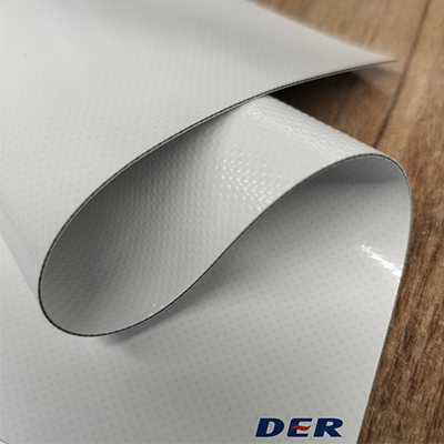
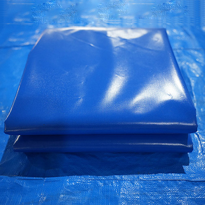
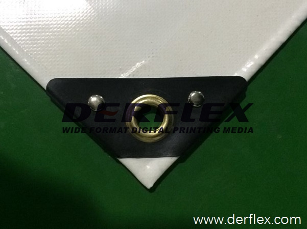
Images are DERFLEX site material and finishing references. They do not document the successive stages of one machinery-cover project.
For the wider fabrication range, see DERFLEX customized PVC tarp products. Agree which fabric, panels, closures and loose accessories are included in the quotation.
Equipment interface review
A fitted equipment cover has to follow the installation route as well as the final outline. The following are design questions and possible construction responses; the project drawing and sample trial determine the selected solution.
On a small screen, scroll the table horizontally to compare all four columns.
| Equipment interface | What the drawing must locate | Construction to review | What to check on the first article |
|---|---|---|---|
| Projecting control box | Full projection, corners, door swing and required access. | Shaped panel or gusset; local access flap if specified. | Cover clears the box during fitting; access works without pulling another area out of position. |
| Fixed pipe or connected cable | Exit coordinates, diameter, routing and whether the connection can be disconnected. | Split opening or closable entry with an agreed weather detail. | The cover can be installed without disconnecting a fixed service; closure does not pinch the connection. |
| Base anchors or skid | Anchor location, permitted strap route and hardware clearance. | Located eyelets, reinforced loops or adjustable straps. | Fasteners reach their intended anchors and load the specified reinforced areas. |
| Bracket or sharp edge | Contact footprint and movement during installation and removal. | Clearance, an abrasion patch or separately agreed edge protection. | Contact is assessed with the actual equipment; the cover does not bridge tightly across an exposed sharp edge. |
| Service door or inspection point | Opening boundary, operating direction and access frequency. | Access panel, zipper or flap positioned away from conflicting straps. | The required operation is possible in the approved covered condition. |
| Top surface or heat-sensitive area | Low points, drainage route, vents and equipment restrictions. | Profile adjustment, supported shape or specified ventilation detail. | Review pooling and moisture risks separately from fit; confirm the cover is used in the agreed equipment state. |
First article / Fit, function and revision
Identify the physical sample and its drawing revision before the trial. Record the equipment configuration, fitting sequence and observations in the same review record.
Use the panel or interface reference, a marked photo and a measured location for each issue. Describe the actual interference, gap, closure problem or misaligned fastening rather than writing only “too tight” or “poor fit.”
For time-sensitive handling requirements, agree the trial conditions and record the observed times. Do not turn an unmeasured impression into an efficiency claim.
Where physical equipment is unavailable, a dimensional fixture can support an interim check. Record the features it represents and the actual-machine checks still required.
Keep the original observation alongside the proposed correction. Update all affected drawing views, cut panels and hardware references, then inspect the changed feature and nearby interfaces on the revised sample.
Scroll horizontally on small screens. These are required record fields, not a completed project history.
| Record | Information to retain | Decision supported |
|---|---|---|
| Trial identification | Sample ID, cover drawing revision, equipment reference, configuration and trial date. | Which physical article and machine were evaluated? |
| Fit observation | Feature reference, marked photo, actual dimension or interference and required function. | What must change, and why? |
| Drawing correction | Previous and revised definitions, affected panels, seam or hardware changes and revision reason. | Does the fabrication set contain the same correction? |
| Recheck result | Revised sample reference, same-interface photos, functional result and any remaining issue. | Has the correction resolved the observed problem? |
| Release decision | Accepted configuration, current drawing set, material and hardware references, exceptions, approver and date. | What exactly is authorized for the production order? |
A photo of an installed cover is useful evidence. A release record also needs to identify the drawing, sample and equipment configuration so the next production run can reproduce the accepted fit.
For production-record continuity, use the tarpaulin factory audit and traceability checklist to define which records need to stay with the order.
Before you order
Start with photos, an equipment outline and quantity. Add the information below so the fit and construction review can focus on the actual machine.
This workflow concerns protective covers for the agreed storage or handling condition. Confirm cooling and equipment instructions before covering. Running machinery, hot surfaces, moving parts and required ventilation call for a separate assessment.
Specify how water should shed, how the cover is secured and where abrasion needs to be controlled. Fit approval alone does not validate road transport or exposed-site restraint loads.
Material choice, usable roll width, panel complexity, seam length, reinforcement, closures, fastening hardware, sample revisions, order quantity and packing all affect the scope. Confirm sampling, revision allowances, delivery terms and timing with DERFLEX.
Related questions
Photos and a measured outline can start the review. Add front, side and rear views, measurement units and the location of protrusions, anchors and access points. Photos without dimensions cannot establish scale or provide a complete fabrication definition.
Submit the actual equipment dimensions and show any requested clearance separately. The appropriate allowance depends on the shape, material, fitting route and closures. Agree the finished-cover dimensions and measurement conditions on the cover drawing.
Locate their projection and access needs on dimensioned views. A shaped panel, gusset or split entry may be reviewed according to the installation route. The first article should verify both passage over the equipment and closure in its final position.
No. A fit trial checks the geometry and agreed functions. Weather protection depends on the fabric, seam construction, closures, openings, drainage and installation. Define any finished-cover water check separately, with its conditions and acceptance criteria.
Identify the sample, current cover drawing, equipment model and configuration, trial date and participants. Retain marked photos, measured observations, correction records, recheck results and the final release decision with any accepted exceptions.
Use the released drawing, specified material and hardware, and retained sample as references. Check whether the equipment or accessories have changed before repeating the order. A changed projection, base or service connection can require a fit review and a new cover revision.
Start your cover review
Tell DERFLEX what you need to cover, where it will be used and how many covers are required. Include the overall dimensions and identify the features that must remain accessible.
Attach files in your email to sales@derflex.com. The quote request page accepts your written brief.