



OEM coated textiles · Secondary containment
Flexible Spill Tray & Pallet Liner Fabric for OEM Fabrication
DERFLEX supplies coated fabric rolls for OEMs developing small flexible spill trays, replaceable pallet liners and drum or IBC collection-area liners. Select spill tray liner fabric around the internal geometry, exact liquid exposure and welding process. Review PVC or TPU coated textile directions, contact-side coating and floor protection before committing to bulk material. The fabric is one component: rigid pallets, load-bearing grates, frames and forklift channels require separate specifications.

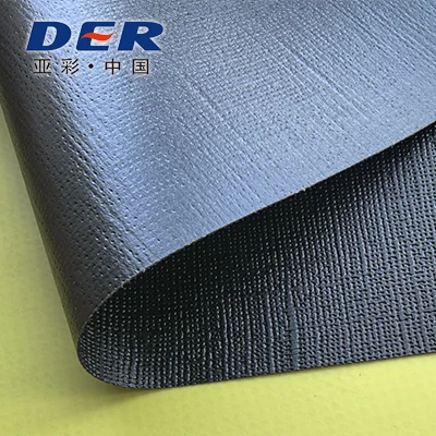
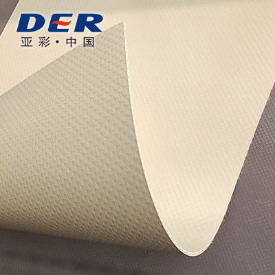
Actual DERFLEX coated fabric swatches. These are material references; appearance and color do not establish liquid compatibility or finished-tray performance.
Component definition
Tray, pallet and IBC liner: define the component
A flexible tray liner is a coated textile barrier formed into a shallow basin or fitted inside a separately supported containment area. The liner retains the specified liquid only when its material, seams, geometry and installation have been validated together.
| Component | What the fabric becomes | What must be defined separately |
|---|---|---|
| Flexible drip or spill tray | A low-wall basin for drips, small releases or a defined maintenance task. | Wall stability, required retention volume, surface protection and handling method. |
| Spill pallet liner | Spill pallet liner fabric formed into a replaceable barrier for a specified pallet sump or support structure. | Rigid body load rating, grate contact points, liner retention and installation clearance. |
| Drum / IBC containment liner | A liner within the collection area beneath or around a container installation. | Container support, required containment capacity, valve clearance and access for inspection. |
For larger portable basins and the broader material category, see spill containment berm fabric.
Fit before capacity
Internal size, wall height and usable containment volume
Specify the finished internal dimensions, the lowest retaining edge and the intended fill level. Cut-panel size, outside tray size and rigid-pallet dimensions describe different things.
Geometry gives a reference, not a tray rating
For an ideal rectangular basin, volume in liters is internal length × internal width × fill depth, all in millimeters, divided by 1,000,000. Flexible walls, folded corners, a sloping floor, supports and objects immersed below the fill line can reduce the available volume.
Confirm usable containment volume on the supported finished assembly, with its intended contents and an agreed fill-test procedure. Outdoor rain allowance and the project’s containment requirement must be assessed separately.
Rectangular geometry check
Illustrative planning tool. Enter internal dimensions and fill depth below the lowest retaining edge.
L × W × h ÷ 1,000,000 = liters
Before losses from corners, wall shape or displacement. This is not usable containment capacity, a material recommendation or a compliance result. The default dimensions are an example, not a DERFLEX model.
Liquid-specific selection
Choose the coating from the actual exposure
PVC and TPU describe material families. Neither name establishes compatibility with every oil, fuel, coolant, cleaning agent or chemical mixture. The exact grade and assembled seam must match the specified contact conditions.
| Review point | PVC coated fabric direction | TPU coated fabric direction |
|---|---|---|
| Starting application | Flexible drip tray material or supported liner where a selected PVC formulation meets the liquid and handling requirements. | Flexible liners where a selected TPU construction meets the liquid, folding and fabrication requirements. |
| Contact-side definition | Specify coating on each face, exposed surface and any finish affecting welding or cleaning. | Specify the TPU grade, coating arrangement and which face contacts the liquid. |
| Fabrication check | Evaluate seams and folded corners on the proposed equipment with the chosen coated faces. | Evaluate the particular TPU construction on the proposed RF/HF or thermal welding process. |
| Approval evidence | Test the named liquid or mixture at the agreed concentration, temperature and contact duration. Include relevant coating, seam, flexibility and leak checks after exposure. A generic resistance chart is only a screening aid. | |
Explore chemical-contact PVC material selection and oil-resistant TPU coated fabric directions. The broader TPU containment fabric guide covers larger spill-control constructions.
Specify both faces
Contact-side coating, floor reinforcement and corner folds
Do not select the liner by GSM alone
Total fabric mass does not identify the thickness or chemistry of the liquid-contact coating. Agree the base textile, coating on each face, total thickness and tolerances, then link those details to the approved sample and material grade.
Protect the floor at the actual contact points
Identify drum rims, pallet ribs, grate feet, abrasive ground and trapped debris. Define a compatible underlay, wear layer or reinforcement where the assembly requires it. Keep added layers from hiding damage or obstructing inspection; any bonded patch must also suit the liquid and joining process.
Allow room for the fold
When specifying collapsible spill tray fabric, account for corner stacks and welded allowances: they can make a liner tight even when the nominal floor dimensions appear correct. Show the fitted support, corner clearance, coated face orientation and folding sequence on the drawing.
- Contact face: identify it on the roll and conversion drawing.
- Mechanical direction: record warp and weft where strength requirements or panel orientation matter.
- Repeated storage: validate the chosen fold pattern after exposure and cleaning.
Fabrication interfaces
Welded corners, support pockets and replaceable liners
The corner combines liquid pressure, folded material and local handling stress. Review it as part of the finished assembly, rather than treating a flat seam trial as proof of a complete tray.
Define the continuous liquid barrier
Show the floor-to-wall transition, corner overlap and weld termination. Keep unsealed stitching, cut edges and hardware penetrations out of the retained-liquid zone unless the complete sealing detail has been validated. Folded self-supporting walls and separately supported walls need different drawings.
Trial the weld on the production material
Record the coated faces being joined, equipment, tooling, overlap, process settings and acceptance criteria. Validate the actual multi-layer corner as well as representative straight seams. Use TPU fabric welding guidance to prepare a material and process discussion; there is no universal temperature setting for every coated construction.
Separate the support from the liner function
Define pockets for stays, wire or removable supports without opening a leak path through the basin. Specify support ends, abrasion protection, insertion clearance and retention. Pockets are a design option to evaluate, not a claim that every fabric can hold an unsupported wall upright.
Design replacement as an installation task
Provide the rigid sump’s inside dimensions, grate arrangement and retention points. The liner should seat without being pulled across sharp corners or pinched beneath supports. Confirm access for inspection, removal and replacement with a fitted prototype.
From drawing to roll purchase
OEM roll width, sampling and specification approval
Ask DERFLEX to review the tray drawing and liquid conditions against a proposed coated fabric construction. Agree the usable roll width before final nesting: nominal width alone does not determine how many complete liner panels fit.
| Specification item | What the OEM should provide or approve |
|---|---|
| Application & drawing | Component type, drawing revision, finished internal dimensions, corner details, support interfaces and planned quantities. |
| Material identity | Selected grade reference, PVC or TPU construction, base textile, face orientation and retained approval sample. |
| Coating & dimensions | Contact-side definition, total mass in g/m², thickness in mm, tolerances and agreed measurement methods. |
| Roll format | Usable coated width, edge trim, roll length, splice policy, winding direction, core and packing requirements. |
| Liquid exposure | Liquid identity, concentration, mixture, temperature, duration, exposure mode and cleaning procedure. |
| Conversion & assembly | Cutting layout, welding method, corner stack, support pockets, floor reinforcement and installation sequence. |
| Validation & records | Agreed test plan, seam and corner acceptance, assembled leak and fill checks, fold checks, grade and batch identification. |
| Commercial basis | Sample scope, trial quantity, bulk volume, color, destination and required delivery date. Confirm MOQ, lead time and terms in the quotation. |
For related roll-material applications, see composite materials for flexible containers. This tray page focuses on shallow basins and replaceable liners, rather than primary storage bladders.
Cost variables: coating construction, usable width and cutting yield, color and finish, sample development, order volume, roll packing and delivery conditions. Finished-liner conversion is a separate scope to define with the fabricator.
An approval sequence for your OEM program
Approve the liner, not only a fabric swatch
- GATE 01 / DRAWING
Fit & interfaces
Freeze the internal dimensions, wall support, corner layout, contact side and support-system boundary.
- GATE 02 / MATERIAL
Exposure trial
Identify the material batch and compare unexposed and exposed samples under the agreed liquid conditions.
- GATE 03 / PROTOTYPE
Corner & assembly
Check welds, fitted supports, leakage and measured retention volume on the actual construction.
- GATE 04 / PILOT
Repeatability
Review trial-production variation, installation, folding and cleaning. Retain the approved specification for reorder control.
Set the test methods, durations and pass/fail criteria before testing. Appearance alone cannot demonstrate retained seam strength, barrier performance or suitability for repeated use.
Before you order
Resolve the details that can change the liner
Measure the assembled support
Record the sump interior, corner radii, obstructions and retaining edges. Account for the liner’s coating, folds and seams before approving the finished fit.
Define the required capacity
A drip tray for routine maintenance may not meet the volume needed for a full drum or IBC release. Match the assembly to the project’s containment requirement.
Keep handling loads separate
Define grate support and forklift access independently. A flexible liner is not a lifting sling; do not assume a filled tray can be lifted or dragged.
Specify every opening
Show drain fittings, pockets and fasteners, including their location relative to the fill level. Agree compatibility and leak checks for the entire interface.
Include cleaning and reuse
Record the cleaner and cleaning temperature in the exposure plan. Inspect floors, welds and corners after use; dry and fold to the approved storage method.
Identify site-specific conditions
State ground abrasion, outdoor exposure and minimum deployment temperature. Where flammable liquids or static control are relevant, define the required system properties and evidence separately.
Procurement questions
Flexible spill tray liner fabric FAQ
Is drip tray material different from spill tray liner fabric?
The terms often describe the same shallow-basin material task. Select by the intended liquid, retained volume, support arrangement and reuse conditions. A spill pallet liner also needs to fit the separate sump and grate structure.
Should we specify PVC or TPU for oil and fuel exposure?
Review the exact liquid and candidate material grade. Coating chemistry, exposure duration, temperature, mixtures and the welded assembly determine suitability. A generic PVC or TPU label is insufficient to approve oil, diesel or other fuel contact.
Does a drum or IBC containment liner support the container’s weight?
The support system must carry the container load. The liner provides the specified liquid barrier and must be protected from support contact and puncture. Rigid-pallet load ratings, grates and forklift channels require separate design and documentation.
Can length × width × wall height be used as the rated capacity?
That calculation is an ideal rectangular reference. Usable containment volume depends on fill level, folded corners, flexible wall shape, slope, supports and displacement. Confirm it on the finished installed assembly rather than publishing the geometric result as a rating.
What makes a replaceable pallet liner fit correctly?
Use the actual sump interior and support layout, including corner radii, grate feet and retention details. Allow for coating, seam and fold thickness. Approve a fitted prototype and its removal sequence before ordering replacement quantities.
What should an OEM send for a material review and quotation?
Send a drawing or dimensioned sketch, the liquid list or SDS, exposure and cleaning conditions, proposed welding method, desired roll format and quantities. Include photographs of the support structure and identify the records or tests required for approval.
Start with the application
Send your tray drawing and liquid list for liner material review.
Develop a clear material brief for your flexible tray, drum containment tray liner or IBC collection-area liner. A sketch and support photographs are enough to start the discussion.
Include with your inquiry
- Tray / sump drawing, internal dimensions and support details
- Liquid list, contact duration, temperature and cleaning method
- Welding process and any corner or liner problems to resolve
- Trial and bulk quantities, destination and required documents