


 INDUSTRIAL COATED FABRICS · OEM ROLL SUPPLY
Request a Quote
Mining Equipment Maintenance Containment Mat Fabric
Choose mining containment mat fabric for service-fluid capture on abrasive ground. DERFLEX supplies coated fabric roll material for OEM maintenance spill mats and equipment service containment liners. Map the fluids, ground and contact points; separate the barrier floor from its underlay and wear protection. Qualify the material, welds and representative assembly before approving reuse.
For mining maintenance contractors, heavy-equipment service teams and mobile service-vehicle OEMs. Scope: fabric selection for fluid capture; equipment support requires a separate engineered arrangement.
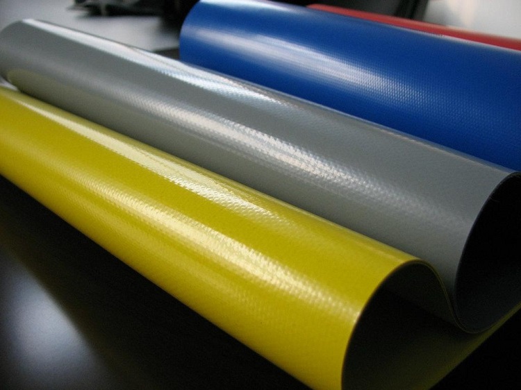
What does the fabric do?
A mining maintenance spill mat uses a qualified barrier floor to intercept service drips and contain collected fluid within its approved assembly. Absorbents may assist recovery, while a separate groundsheet protects the floor from below. A flat sheet alone has no defined liquid-holding capacity on sloping ground.
Map the service zone and expected fluids
Draw the capture area around the maintenance operation, including where the fluid can travel and where the technician needs access.
Mark the actual drip envelope
On an excavator, locate drain points, filters and hose connections relative to tracks and access panels. On a drill rig, include hydraulic service points, hose routes and any nearby support feet. For a mining truck, map the component being serviced and the technician’s recovery route rather than using the vehicle outline as the mat size.
Record ground slope, loose stone, sharp fragments, standing water and access restrictions. Mark where trays, removed parts and tools will sit. Include the clear space needed for the proposed wall or edge detail and for collecting liquid without pulling on the liner.
This page addresses liquid capture during servicing. Use the broader mining tarp application guide for stockpile, transport and equipment-cover requirements.
capture zone
tool zone
On smaller screens, scroll horizontally to read all columns.
| Exposure to identify | Information to supply | Selection consequence |
|---|---|---|
| Engine or hydraulic oil | Product name, additives, service temperature and time before recovery. | Evaluate the exact coating and welded assembly against the actual oil; an oil-family label is insufficient. |
| Fuel or fuel mixtures | Fuel specification, blend, expected contact duration and whether contact is occasional or sustained. | Require grade-specific compatibility evidence. A waterproof PVC or TPU fabric is not automatically fuel-qualified. |
| Coolant, degreaser or mixed fluids | Concentration, dilution, safety data sheets and the intended cleaning sequence. | Review each exposure and any relevant sequence or mixture; a result for one fluid cannot approve the others. |
| Rainwater entering the zone | Outdoor exposure, task duration, usable basin geometry and liquid recovery arrangements. | Allow for additional water and displaced volume. Recover potentially contaminated liquid through the site procedure. |
Use the chemical-contact fabric selection guide to structure the exposure discussion. The final decision belongs to the identified material grade and finished assembly.
Separate barrier floor, groundsheet and sacrificial wear layer
A thicker sheet does not remove every damage mechanism. Specify protection above and below the liquid barrier.
The barrier floor needs a continuous, compatible coating and qualified welded details. The underlay addresses contact with the prepared ground. A removable top wear layer addresses a defined tool or component contact zone and must allow fluid to reach the capture area without concealing damage.
A permeable groundsheet can cushion or separate surfaces, but it cannot replace the liquid barrier. Absorbent pads serve another role: collecting compatible liquid for removal. Their capacity and change-out procedure need to be considered separately.
For the floor-to-wall transition, corners and perimeter format, see fabric selection for raised-edge containment construction.
Replaceable protection in approved tool or component contact zones. Lift out for cleaning and inspection.
Qualified coated fabric with welded seams, corners and perimeter details forming the capture assembly.
Separate underlay selected around the actual ground profile and debris conditions.
Choose by evidence, not by polymer name or GSM alone. PVC-coated and TPU-coated textiles are material directions to discuss. The selected grade still needs the appropriate exposure, coating adhesion, puncture, abrasion, folding and weld evaluations. No universal weight or thickness qualifies a mining maintenance mat.
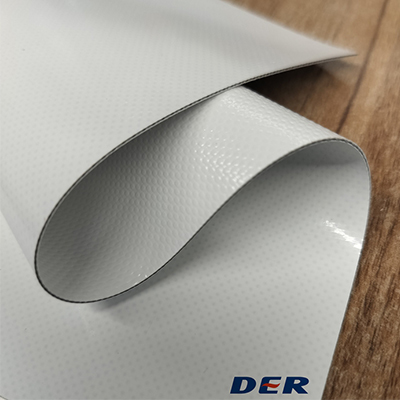 Inspect both faces
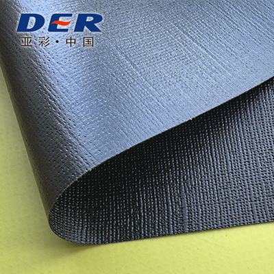 Compare surface finishes
Design for equipment feet and tool contact
Identify each contact point by shape, movement, force and duration. The overall machine weight does not describe the stress at a small foot, sharp part or trapped stone.
Equipment feet, stabilizers and support arrangements
Mark these on the service drawing and resolve the support arrangement independently. Keep unqualified fabric out of the load path. A reinforcement patch or loose board does not create a load rating; adding a pad also changes the interfaces that need assessment.
Removed filters, panels and metal components
Use an agreed protected placement zone with compatible trays or contact protection. Assess burrs, corners, temperature and residual fluid. A wear layer should be replaceable without cutting into or puncturing the barrier floor.
Tool dragging, grit and walking routes
Lift tools rather than dragging them over the barrier. Define any unavoidable sliding contact in the prototype plan. Check grit trapped beneath protection, wet or oily footing, wrinkles and transitions; texture alone does not demonstrate slip performance.
Welds, corners and recovery interfaces
Route joints away from repeated contact where the layout allows. Qualify overlaps, floor-to-wall transitions and any recovery fitting on the actual material. An exposed sewn seam needs an independently qualified sealing arrangement if it forms part of the liquid boundary.
Use the welded and sewn seam strength guide to define joint geometry and failure modes. Strength testing and liquid-tightness checks answer different questions.
Define deployment, folding and cleaning cycles
A reusable equipment service containment liner needs a repeatable handling procedure, including what happens after the fluid is recovered.
- 01 / DEPLOY
Prepare and inspect
Check the selected ground and remove sharp debris. Inspect both barrier faces, place the underlay, unfold without dragging, and confirm the perimeter and recovery route.
- 02 / SERVICE
Monitor the capture area
Keep the agreed contact protection in position. Check fluid accumulation, wall stability, trapped grit and new damage. Recover liquid before it threatens the usable containment volume.
- 03 / CLEAN
Recover, then clean
Collect service fluids and residues through the site’s waste procedure. Use a cleaner and method approved for the grade and assembly; validate brushing, rinsing and drying conditions.
- 04 / PACK
Inspect before folding
Remove the wear layer and check hidden surfaces. Dry the assembly, follow the agreed fold pattern and storage conditions, and record defects before returning it to the service vehicle.
Define the cycle, then test it. Record the lowest handling temperature, fold geometry, seam orientation, cleaning agent, dilution and repeated handling sequence. Do not turn an untested cycle count into a service-life claim. Leakage, exposed reinforcement, coating separation or uncertain contamination requires isolation and assessment before reuse.
Adapt the general tarp cleaning, inspection and storage checklist to the qualified containment material and site contamination controls.
Approve the representative field prototype
Move from material screening to a representative welded sample, then to a controlled trial of the proposed layered assembly. Agree the acceptance criteria before testing.
Freeze the trial configuration
Identify material grade, roll or batch, coating faces, underlay, top protection, wall construction and drawing revision. Record the ground and contact interfaces.
Screen the exposure and fabrication
Use representative fabric and welds. Define the actual fluids, duration, temperature, cleaning sequence and post-exposure checks before accepting a material direction.
Check the realistic damage mechanisms
Agree controlled puncture, abrasion, tool-contact and folding evaluations appropriate to the site. Document fixtures, contact geometry and applied conditions rather than reporting only “heavy duty.”
Trial the service workflow
Use an approved, controlled procedure with recovery measures. Observe deployment, access, fluid capture, cleaning and packing. Recheck the barrier after the handling sequence and record every defect location.
What belongs in the approval record?
- Service-zone drawing and actual ground photographs.
- Layer cross-section, material identifiers and weld map.
- Fluid names, concentrations, temperatures and exposure times.
- Contact-damage, fold and cleaning conditions with raw observations.
- Specimen quantities, test method, acceptance limits and dated photographs.
- Decision, restrictions, revised details and required rechecks.
Material guide, not a field-test report. This page sets out a qualification approach. It presents no measured mine-site trial results or mining-truck drive-over certification.
The coated-fabric testing and buyer checklist helps define evidence for the reinforcement and coating. Add project-specific fluid-contact and finished-assembly checks.
On smaller screens, scroll horizontally to read all columns.
| Evaluation | Record the conditions | Check after the sequence |
|---|---|---|
| Liquid contact | Exact grade, coating face, liquid, concentration, time and temperature; include representative joints. | Swelling, softening, adhesion change, retained properties and leakage against agreed limits. |
| Ground-side damage | Representative ground profile, underlay, specimen stack, fixture, force and repetitions. | Puncture, coating wear, fabric exposure and barrier integrity. |
| Tool / component contact | Approved contact shape, wear layer, placement or sliding motion and duration. | Local cuts, displaced protection, trapped grit and hidden damage. |
| Fold / clean / redeploy | Temperature, fold pattern, joints crossing folds, cleaning method and cycle sequence. | Cracking, weld separation, coating loss, dimensional change and liquid-tightness. |
Before you order
Turn “heavy equipment drip mat material” into a defined roll-fabric specification and a finished-product approval plan.
On smaller screens, scroll horizontally to read all columns.
| Purchase item | Specification to agree | Why it matters |
|---|---|---|
| Construction | Coating polymer and grade, reinforcing textile, coating faces, finish and identification. | Keeps sample approval and repeat supply tied to the same material. |
| Weight & thickness | Nominal g/m² and mm, tolerances and measurement method. | Mass and thickness describe different properties; neither alone establishes contact or barrier performance. |
| Usable width & packing | Clear usable width, roll length, core, roll handling limits and batch labels. | Affects the cutting plan, joint positions, handling and order utilization. |
| Exposure & reuse | Liquid list, temperature, contact duration, cleaning and minimum folding conditions. | Defines the evidence required for the intended service envelope. |
| Welding & assembly | Fabricator’s equipment, weld faces, joint geometry and sample acceptance plan. | Connects the roll material to the floor, corners and perimeter design. |
| Performance records | Applicable methods, directions, specimen details, reporting units and acceptance limits. | Allows relevant, comparable results rather than unrelated headline values. |
Confirm the supply boundary
This inquiry starts with coated fabric roll goods for OEM fabrication. Specify cut panels or finished welded products separately if required; agree the actual scope in the quotation. Underlay, absorbents, wear pads, supports, recovery equipment and installation are separate items unless expressly included.
Quote variables include construction, usable width and yield, quantity, color, required documentation, packing and destination. Confirm MOQ, sample arrangements and lead time for the selected order.
Release against an approved sample
Approve the fabric reference, drawing revision, weld details and field-trial conditions before bulk release. Changes in fluid, contact geometry, cleaning chemistry or ground protection should trigger a suitability review.
Keep the prototype records with the material and assembly specification. Define inspection, permitted repair and retirement decisions for the contamination risk; a general cover repair procedure does not automatically qualify a containment repair.
Mining maintenance mat fabric FAQ
Is a mining maintenance spill mat the same as a mining tarp?
The primary task differs. A maintenance mat captures service fluids beneath or beside equipment, so liquid compatibility, barrier integrity, ground damage and recovery matter. A mining tarp may instead cover stockpiles, loads or machinery. A cover specification does not qualify a containment mat.
Should I choose PVC or TPU containment mat fabric?
Compare identified grades against the same fluids, ground contact, fold conditions, welding process and acceptance criteria. Neither polymer name establishes universal resistance to oil, fuel or degreasers. Representative fabric and welded samples are needed before approving the finished assembly.
Can a mining truck, jack or stabilizer sit directly on the fabric?
No such rating is established here. Keep an unvalidated mat out of vehicle, jack and support load paths. A suitable arrangement needs review of the complete stack, ground, contact geometry and loading; fabric tensile strength or a patch alone cannot establish load capacity.
Does a groundsheet or absorbent layer replace the barrier floor?
No. The groundsheet protects from below and may be permeable. An absorbent layer collects compatible fluid but has its own capacity and replacement limits. The qualified barrier floor and its perimeter provide the intended liquid-containment boundary.
How many folding and cleaning cycles will the mat withstand?
A cycle limit needs evidence for the particular material and assembly, including temperature, fold pattern, seam orientation, cleaning agent and contact wear. Agree a repeatable validation sequence and inspection criteria; no service-life or cycle-count result is claimed on this page.
What should I send for a fabric recommendation and quote?
Start with ground photographs, a service-zone sketch, the fluids and cleaning agents, and equipment or tool contact points. Add dimensions, handling temperatures, reuse frequency, your fabrication process, quantity and destination. DERFLEX can then discuss a candidate roll construction and sample evaluation scope.
Share ground photos, service fluids and equipment contact points.
Bring the actual maintenance conditions to the material discussion. A clear service brief helps connect the coated fabric, protection layers and prototype acceptance plan.
- Ground photos, slope and sharp-debris conditions
- Equipment outline, service points and capture dimensions
- Fluid names, cleaning agents and contact durations
- Feet, tools and component placement zones
- Fold, cleaning and storage conditions
- Fabrication process, order quantity and destination
Send the project brief through the DERFLEX inquiry page. Sample scope, material specification and supply terms are agreed for the project.