News
Company News

Refueling & Fuel Transfer Containment Fabric | DERFLEX

Update:2026/10/21 18:31:07 Views:
Skip to material guide
Fuel transfer · Secondary containment · OEM

Refueling Pad & Fuel Transfer Containment Fabric

Specify refueling pad fabric around the fuel, the capture zone and the time a spill may remain in contact. DERFLEX supplies coated fabric rolls for OEMs developing hose-connection drip trays, pump containment pads and refuelling work-area liners. Review candidate PVC or TPU constructions against the exact fuel blend, welded assembly and access requirements before production approval.

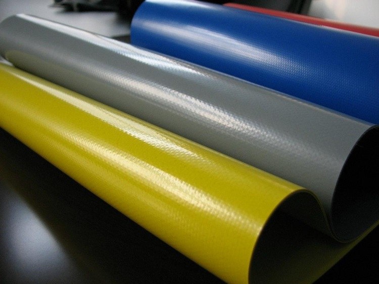
Yellow, grey and blue DERFLEX coated fabric samples
Start with the material. Qualify the assembly.Actual DERFLEX fabric reference. Appearance and color do not establish fuel compatibility or a vehicle-load rating.
01
Locate the capture zone

Coupling, pump skid or vehicle fueling point.

02
Define the fuel exposure

Blend, temperature, dwell time and cleanup.

03
Approve the finished detail

Seams, corners, entry and site interfaces.

01 / Map the operation

Define hose, pump and refueling capture zones

One material inquiry can cover three very different assemblies. Mark each source of drips, the expected spill path and the working footprint on your layout.

A / HOSE CONNECTION

Disconnect drip tray

Position the tray beneath the coupling break and the place where a wet hose end is parked. Allow for hand access, hose movement and drips from both halves of the connection.

Design focus: a stable low wall, sealed corners and a footprint that stays under the drip path.

B / PUMP GROUP

Pump containment pad

Capture leaks from seals, filters, valves and service connections. Keep collection areas visible and reachable without loading a soft liner directly under sharp skid feet.

Design focus: load-spreading interfaces, underside protection and service access.

C / VEHICLE WORK AREA

Refueling work-zone liner

Locate the filler, nozzle handling area and hose route within the intended capture footprint. Identify tire paths and turning space before choosing an entrance detail.

Design focus: entry-wall behavior, traffic wear and effective containment capacity.

Schematics only; not to scale. These concepts are not installation drawings, a drive-over approval or evidence of an actual DERFLEX refueling project.

02 / Specify the exposure

Identify the fuel blend and spill dwell time

Fuel transfer containment fabric is a reinforced, coated textile used to fabricate a secondary capture surface around transfer equipment. Suitability depends on the exact fuel, contact temperature, time before recovery and finished seams. A waterproof or oil-resistant label alone does not establish suitability for diesel transfer.

Describe the liquid as it is supplied.

Send the current fuel SDS and supplier product designation. State the biodiesel or other blend content where known, relevant additives and any other liquids that may enter the same pad. Treat a change of fuel supplier or blend as a reason to review the approval scope.

Brief drips
Define recurring wetting at coupling disconnects, time to wipe or recover liquid, and the number of daily transfer cycles.
Retained spill
State the maximum credible time from release to recovery, including unattended periods. Do not specify only the duration of the pumping operation.
Repeated use
Include cleanup fluid, dilution, wash temperature, drying, folding and the condition in which the pad is redeployed.
03 / Turn the site brief into a fabric specification

Select floor, sidewalls and access layout

A hose connection drip tray fabric may need compact folding and clean corner welds; a pump pad adds concentrated support loads; a vehicle refuelling containment material needs an independently validated traffic arrangement. Choose each component around its own duty.

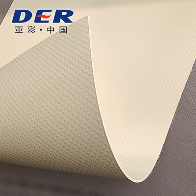
Beige DERFLEX coated textile folded to reveal its backing
Coating and backingTPU fabric reference from the DERFLEX range. Grade-specific fuel evidence is required.
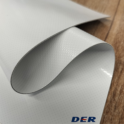
Grey DERFLEX vinyl coated fabric folded over a wood surface
Wetted face and foldPVC material reference. Review formulation, fold behavior and weld-facing surfaces.
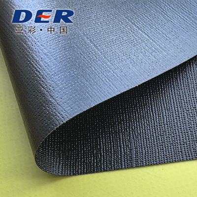
Grey and black faces of a DERFLEX industrial coated textile
Ground-contact faceInspect both faces and discuss underside protection. This image is not a puncture test.

Specification framework, not a stock-grade TDS. On small screens, scroll the table horizontally.

What to specify for a fuel-transfer containment assembly
Component / propertyProcurement decisionEvidence or drawing to agree
Material constructionCandidate PVC or TPU coating, polyester or other reinforcement, wetted face and backing.Exact grade, coating structure and fuel-exposure approval scope. Polymer family alone is insufficient.
Mass, thickness & widthGSM, thickness in mm, usable roll width and cutting allowance for the intended layout.Nominal values, tolerances and measurement method on the approved order specification. GSM does not define thickness.
Containment floorSeam placement, ground abrasion, hose dragging and points of concentrated load.Panel map, underlay and wear-layer arrangement; tensile, tear, adhesion and contact-damage criteria.
Walls & cornersWall support, low-edge geometry, reinforcement and repeated folding.Corner sections, production weld coupons and leak checks after fuel exposure and handling.
Access detailHand access for a tray; skid interfaces for a pump; tire path and entrance behavior for a vehicle pad.Assembly-specific load and cycle trials. A fabric tensile result is not a drive-over load rating.
Weld processFabrication method, weld-facing surfaces, overlap and repair compatibility.Trials on the intended equipment with the selected grade. Set process parameters from validated samples.
Static-control interfaceRequired electrical behavior, conditioned test method and any designed connection detail.Material and assembly measurements within the site's approved static-control design.
OEM supplyRoll quantity, usable width, color, roll identification, core and protective packing.Approved sample and order revision; confirm MOQ, lead time and document scope at quotation.

No generic fuel-contact duration, temperature limit, chemical rating or vehicle capacity is implied. Request the technical data and relevant evidence for the exact proposed grade.

Corner + access concept / schematic ABC
Conceptual geometry only. The low edge illustrates an access feature that must be resolved in the approved design. It is not a validated vehicle entrance, finished product or capacity drawing.
  • A

    Keep wear layers distinct from the barrier.

    A ground underlay protects against site debris; a top wear layer addresses boots, hose movement or traffic. Define whether these are separate, replaceable components and keep the barrier inspectable.

  • B

    Resolve the floor-to-wall corner.

    Provide the weld overlap, fold direction and reinforcement section. Assess leak paths and peel loading at corners after exposure and repeated packing, rather than approving only a straight seam.

  • C

    Review the entrance as its own assembly.

    Low or collapsible edges alter the retaining level. Vehicle access needs its own wheel-load, tire-path, support and repeated-crossing validation. Keep hose routing from holding a retaining wall down.

04 / Site coordination

Coordinate static-control requirements with the site

Static control is a system requirement. The responsible site team should define the fuel-transfer hazard, applicable operating requirements and the roles of hoses, pumps, vehicles, operators and containment components.

Where specified, fabric electrical properties need an agreed test method and conditioning. An antistatic label does not establish a safe bonding or grounding path, and a flame-retardant result does not establish explosion protection.

  1. Define the required material behavior.State resistance or resistivity requirements, units, tested face, electrodes and environmental conditioning. Do not copy a limit from another application.
  2. Agree the complete connection design.Have the site specialist specify the intended bonding or grounding arrangement, contact points and verification. Do not improvise a connection by clamping through an ordinary coated sheet.
  3. Include service conditioning.Where electrical behavior is required, evaluate relevant seams and interfaces after the agreed fuel, cleaning, folding and wear exposure.
05 / From sample to purchase approval

Sample the assembly before production approval

Approve a representative construction tied to a drawing revision and material grade. A clean-looking swatch cannot prove a finished tray or pad will retain the specified liquid.

  1. Freeze the brief

    Record the fuel SDS, maximum spill dwell time, temperature, cleanup cycle, capture zone and site-defined acceptance criteria.

  2. Compare material samples

    Review candidate coating and reinforcement. Preserve an unexposed reference and define the exposure and measurement plan with the appropriate test provider.

  3. Build the critical details

    Include a production weld, a low-wall corner and any access or fitting detail. Evaluate containment, handling and relevant retained properties after conditioning.

  4. Approve the first article

    Check dimensions, seam map and assembly performance against the approved drawing. Review wheel access, electrical requirements and site capacity separately where applicable.

The approval record should travel with the order.

Link the material grade and roll or batch reference to the drawing revision, weld process, exposure record, inspection results and retained sample. Agree how a material, fuel, construction or process change triggers review before repeat production.

Before you order

Send a usable fuel-transfer brief.

  • Fuel: current SDS, product name, blend details and other liquids likely to contact the pad.
  • Exposure: liquid and ambient temperature, longest expected dwell time and recurring drip frequency.
  • Layout: pump and hose positions, coupling break points, nozzle handling area and photos or a marked sketch.
  • Construction: finished internal dimensions, low-edge and corner sections, underlay and wear-layer needs.
  • Site requirements: required capture capacity, static-control specification and vehicle access conditions.
  • Purchase: roll or component scope, quantity, usable width, destination, required documents and planned approval date.
Buyer questions

Refueling containment fabric FAQ

Practical answers for mining refueling integrators, oilfield service companies, pump and hose OEMs, and spill-control product manufacturers.

Is diesel spill pad material an absorbent pad?

The fabric discussed here forms a liquid-retaining barrier for a tray or containment pad. It is not an absorbent. An approved assembly may use compatible absorbent media inside it, but absorbency, retention and available containment volume need separate assessment.

Should I choose PVC or TPU for a diesel transfer pad?

Shortlist the exact formulation against the fuel blend, temperature, dwell time, welding route and handling duty. Neither polymer name establishes suitability for all diesel, biodiesel, gasoline or additive mixtures. Compare relevant exposure evidence for both the material and proposed seams.

How long can spilled fuel remain on the fabric?

Use only a contact duration supported by evidence for the chosen grade, fuel and conditions. State your longest credible recovery delay before testing. A short splash assessment does not support continuous contact or a general storage-life claim.

Can vehicles drive over the containment pad?

Only when the actual floor, wall, entrance and protective-layer arrangement has been validated for the intended vehicle and traffic duty. Fabric strength or GSM alone does not establish a wheel-load rating. Check the retaining level and integrity after repeated crossings.

Does antistatic fabric replace bonding and grounding?

No. Material electrical behavior is one part of the site's static-control design. The responsible site specialist must define the necessary equipment connections and verification for the fuel-transfer operation. Do not infer explosion protection from an antistatic or flame-retardant fabric description.

Is this the same material specification as a fuel bla, dder?

A bladder holds fuel as a primary container; a refueling pad provides secondary capture around transfer work. Pressure, seams, fittings and exposure duty can differ. Qualify each construction for its specific role, even if both start from a reinforced coated textile.

Start with the actual transfer operation

Submit the fuel SDS, transfer layout and expected spill duration.

Tell DERFLEX whether you are developing a coupling drip tray, pump containment pad or refueling work-area liner. Add quantity and destination to begin a focused material and sample discussion.

Request a Quote

Use the quote page to introduce your project, or email the SDS and layout to sales@derflex.com.

Consulting Services
+86-021-54361792 / 54361798
Email
sales@derflex.com