News
Company News

ETFE Facade Membrane for Lightweight Building Envelopes | DERFLEX

Update:2026/7/13 2:08:02 Views:
Architectural membrane material supply for international projects Request A Quote
Lightweight facade material · project specification support

ETFE Facade Membrane

Transparent, translucent, printed and illuminated ETFE film for expressive building skins—developed around the facade geometry, wind actions, daylight target, frame interface and fabrication route of each project.

ArchitectsTransparency, pattern, module rhythm and nighttime identity
Facade ContractorsFrame, clamp, seam, access and installation coordination
Membrane FabricatorsWelding trials, roll yield, panel nesting and handling
EPC & ProcurementScope clarity, documents, packing and delivery sequence
Owners & DevelopersDaylight, appearance, maintenance and replacement planning
Facade-specific material logic

What Is an ETFE Facade Membrane?

An ETFE facade membrane is a thin fluoropolymer film used as part of a lightweight external building envelope. The foil may be tensioned as a single skin, supported by cables, or welded into two- or multi-layer pneumatic cushions held by an aluminium perimeter system. In architectural procurement, the terms ETFE facade membrane, ETFE foil facade and ETFE film cladding are often used for closely related material directions.

The membrane is only one element of the completed facade. Panel geometry, foil stress, edge clamping, weld design, air supply, drainage, fire strategy, thermal bridges, movement joints, access and connection to the primary structure must be coordinated as a complete envelope. This is why a facade inquiry should begin with drawings and performance targets rather than only a price per square metre.

Why facade design differs from roof design

A vertical ETFE facade is exposed to alternating wind pressure and suction, driven rain, stack effects around cavities, visual inspection from both inside and outside, and close-range night lighting. It may avoid some roof-specific snow or ponding concerns, but it introduces its own requirements for vertical water management, cavity ventilation, edge termination, maintenance access and interfaces with doors, opaque walls and glazed zones.

Material selection should be connected to facade orientation, module size, local wind data, transparency target and the appointed system engineer’s calculations.
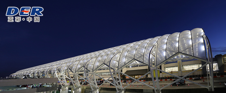
DERFLEX ETFE architectural membrane used in a transparent illuminated building envelope
Transparent and illuminated envelope direction Clear, printed or translucent ETFE can support daylight by day and a recognizable facade identity after dark. Final appearance should be verified with physical samples and project mock-ups.
System directions

Four Ways ETFE Can Shape a Facade

Each route creates a different relationship between transparency, structure, thermal performance, fabrication complexity and architectural expression.

S

Single-Layer Stressed Skin

A single ETFE foil is pre-tensioned within a frame or over a support system. It offers a visually light enclosure with a comparatively simple build-up, while thermal and acoustic performance remain limited and must be assessed at system level.

C

Cable-Supported Foil

Cables or secondary members help control larger membrane fields and facade curvature. Cable spacing, pre-stress, edge details, movement and local load transfer require coordinated engineering.

2–4

Pneumatic Cushion Facade

Two or more welded layers form pressurized modules. Layer count, cushion rise, frit position and air-control design can be adjusted to pursue daylight, shading and thermal targets.

L

Printed & Illuminated Skin

Frit patterns, tint directions and integrated lighting can turn the facade into a visual feature. Print coverage, color tolerance, viewing distance, LED heat and maintenance access should be reviewed through a mock-up.

Product image display

ETFE Material in Lightweight Architectural Forms

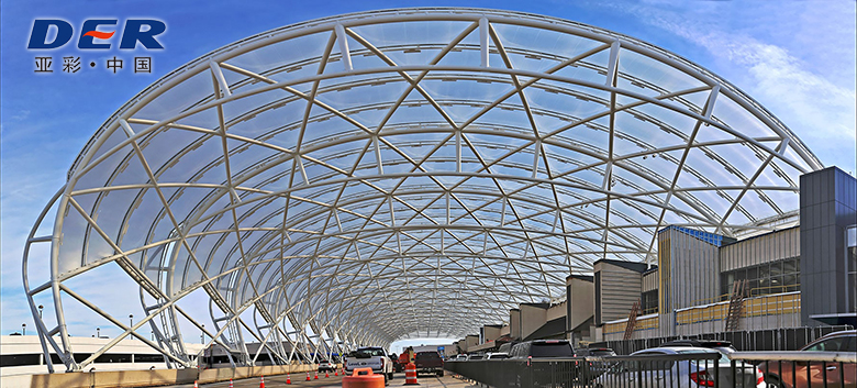
DERFLEX site imagery shows the visual direction of transparent foil envelopes and the supporting structures that must be coordinated with the membrane.

Facade engineering checkpoints

Performance Depends on More Than the Film

The following topics should be addressed before a material order is separated from the facade-system design.

Wind

Positive Pressure & Suction

Facade orientation, corner zones, building height, local terrain and panel dimensions influence foil stress, cushion shape and support spacing.

Water

Vertical Drainage & Interfaces

Driven rain, perimeter channels, sill details, secondary drainage and transitions to adjacent cladding require a coordinated water-management route.

Movement

Frame Tolerances & Deflection

Primary-structure movement, thermal expansion, fabrication tolerances and gasket compression should be accommodated without overstressing the foil or seals.

Climate

Daylight, Glare & Solar Gain

Clear film maximizes visual openness, while frit patterns, translucent layers or tint directions can be considered to modify glare and solar transmission.

Operation

Access, Inspection & Replacement

Catwalks, façade-access equipment, removable caps, safe working zones and individual module replacement should be considered during design.

Compliance

Fire, Smoke & Local Codes

Use the exact film or assembly test information required by the destination market. Avoid generic terms such as “fireproof”; project consultants should review applicable classifications.

Specification framework

Information to Define Before Quotation

This table is an RFQ starting point. Final values should be confirmed by drawings, approved samples, applicable tests and responsible engineering review.

Product DirectionETFE facade membrane, architectural ETFE foil or ETFE film for transparent and translucent building-envelope applications.
Material StructureExtruded ETFE fluoropolymer film without woven reinforcement. Finished behavior depends on the foil, welds, clamping, frame, air system and project engineering.
Common Thickness Discussion100 μm, 150 μm, 200 μm and 250 μm are common early-stage discussion points. The final layer-by-layer thickness must follow stress calculations, module dimensions and the selected system.
Facade SystemSingle-layer stressed skin, cable-supported foil, two-layer cushion, three-layer cushion, specialist multi-layer cushion or feature-envelope component.
AppearanceClear/natural, translucent, white direction, project tint, dot/frit print, pattern print or lighting-oriented visual concept, subject to feasibility and sample approval.
Optical DirectionCertain clear single-film directions may provide very high visible-light transmission. Actual transmission, haze and solar values vary by grade, thickness, color, print coverage and number of layers.
Facade Design InputsElevation drawings, module size, building height, orientation, design wind actions, support spacing, cavity concept, openings, interfaces and maintenance strategy.
Fabrication InputsWelding equipment and seam trials, panel nesting, roll width, splice policy, print registration, handling limits and the fabricator’s acceptance criteria.
DocumentationRequired technical data, inspection records, test information, labels, packing list and project-specific documents should be identified before order confirmation.
DERFLEX Support ScopeMaterial-direction review, film thickness discussion, sample coordination, visual and print communication, roll quotation, packing, labeling and export delivery planning.
Specialist ResponsibilityStructural calculations, facade system engineering, cushion fabrication design, aluminium profiles, inflation controls, drainage, installation and local-code approval remain subject to the agreed project scope and qualified specialists.
Procurement clarity

Separate the Material Scope from the Installed Facade Scope

Clear responsibility boundaries help architects, contractors, fabricators and procurement teams compare quotations on the same basis.

Film-Supply Conversation

DERFLEX can organize the ETFE material discussion around the required facade appearance, thickness direction, sample, roll format and commercial documentation.

  • Clear, translucent, tinted or printed film direction
  • Layer-by-layer thickness discussion
  • Physical sample and visual reference confirmation
  • Roll width, core, length, splice and edge condition
  • Labeling, protective packing and export documents
  • Repeat-order reference and agreed inspection points

Complete-System Conversation

A finished ETFE facade normally involves several specialist disciplines that may be outside a film-only quotation.

  • Facade engineering and structural verification
  • Cutting pattern, welding and cushion fabrication
  • Aluminium profiles, gaskets and thermal interfaces
  • Air supply, monitoring, controls and redundancy
  • Drainage, cavity ventilation and adjacent cladding details
  • Installation, testing, commissioning and maintenance access
Application planning

Where ETFE Facade Membrane Is Commonly Considered

ETFE is most relevant when the project values a lightweight, daylight-oriented and visually distinctive facade rather than a conventional opaque wall.

Sports

Stadium & Arena Facades

Printed or illuminated modules can create a recognizable venue envelope while keeping the cladding direction light.

Transport

Airports & Railway Hubs

Bright circulation zones, entrance walls and terminal enclosures can combine weather protection with visual openness.

Commercial

Retail & Entertainment

Shopping centres, leisure destinations and exhibition venues can use pattern, tint and lighting as part of the brand experience.

Public

Cultural & Civic Buildings

Museums, libraries and public halls may use ETFE to create a translucent outer skin or lightweight feature wall.

Nature

Botanical & Learning Spaces

Daylight-focused building skins can support conservatories, educational environments and research facilities, subject to climate design.

Upgrade

Lightweight Extensions

Projects with structural-load sensitivity may evaluate ETFE for new envelope zones around existing buildings or courtyards.

Early material comparison

ETFE Facade vs Other Envelope Directions

No single facade material fits every building. Compare the project objective before deciding which route deserves detailed engineering.

Decision Factor

Visual GoalWhat kind of envelope identity is required?
Weight DirectionHow sensitive is the supporting structure?
TransparencyHow much clear view or diffused daylight is needed?
System QuestionsWhat must be engineered beyond the material?
Strong Candidate WhenWhat project priority points toward this route?

ETFE Membrane

Light, clear, translucent, printed or illuminated building skin with flexible module geometry.
Very lightweight foil direction, subject to the complete frame and system design.
High daylight potential; actual optical values depend on film, print and layers.
Foil stress, welds, clamps, cushions, air system, drainage, access and code approval.
Daylight, low envelope weight and expressive form are central to the concept.

Glass Curtain Wall

Rigid, crisp and familiar transparent facade with conventional glazing expression.
Heavier panel direction with corresponding mullion, anchor and primary-structure demands.
Clear views are possible; coatings, frits and shading influence heat and glare.
Glass make-up, safety, sealants, pressure equalization, drainage, anchors and replacement access.
Rigid transparency, acoustic mass, established curtain-wall detailing or view quality is prioritized.

Opaque Fabric / Metal

Opaque or perforated shade, solid color, metallic texture or strong v, isual screening.
Often lightweight relative to glass, with a wide range depending on material and support.
Usually diffused, screened or opaque rather than glass-like transparency.
Tensioning or panel fixing, corrosion, ventilation, backing wall, joints and maintenance.
Shade, privacy, simple branding, opaque enclosure or a tighter material budget is more important.

DERFLEX workflow

From Facade Brief to Supply-Ready Film Specification

A staged approval process reduces ambiguity between the architect, facade contractor, fabricator, procurement team and film supplier.

01

Share the Envelope

Elevation, system concept, module sizes, quantity, location and project stage.

02

Define the Visual Target

Clear, translucent, tint, frit pattern, lighting concept and viewing conditions.

03

Coordinate the Film

Layer thickness, roll width, fabrication route, print feasibility and documents.

04

Approve Samples

Physical visual reference, print layout, color tolerance and welding trial where needed.

05

Control Supply

Written specification, inspection points, labels, packing and delivery sequence.

FAQ

ETFE Facade Membrane Questions

Practical answers for architects, facade companies, membrane fabricators, developers and procurement teams.

Is an ETFE facade membrane the same as an ETFE cushion facade?

No. ETFE facade membrane is a broad material and application term. A cushion facade is one system type made from two or more foil layers welded into pressurized modules. A facade may also use a single tensioned layer or a cable-supported foil system.

What thickness of ETFE film is used for a facade?

Early project discussions commonly include 100, 150, 200 and 250 μm film. The final thickness for each layer depends on module dimensions, wind actions, foil stress, cushion geometry, printing, fabrication and the system engineer’s calculations.

Can ETFE facade membrane be printed or colored?

Printed frit, dot and project-based pattern directions can be discussed, along with translucent or tint options subject to production feasibility. Print coverage and layer position affect daylight, glare, solar transmission and visual consistency, so sample and mock-up approval are recommended.

Can lighting be integrated behind an ETFE facade?

Yes, illuminated ETFE envelopes are possible. The lighting designer and facade specialist should coordinate LED spacing, access, heat, reflection, print, foil appearance, maintenance and the expected view from different distances before finalizing the material.

Does an ETFE facade require an inflation system?

Only pneumatic cushion facades require controlled air supply. A single-layer stressed skin does not use continuous cushion inflation, although it still requires designed pre-tension, edge clamping and structural support.

What should be sent to DERFLEX for a useful quotation?

Send the facade elevation or concept, system type, module dimensions, layer count, thickness direction, clear or printed appearance, estimated quantity, roll preference, fabrication location, destination market, required documents and target delivery stage.

Discuss Your ETFE Facade Material Requirements

Share the elevation, system concept, film thickness direction, visual target, project quantity and destination. DERFLEX will review the material-supply route and identify the information still needed from the facade engineer or fabricator.

Product descriptions and ranges are for preliminary purchasing communication. Final material values, system performance, tests, compliance and project suitability must be confirmed in writing for the selected specification, assembly and destination market.
Consulting Services
+86-021-54361792 / 54361798
Email
sales@derflex.com