Freeze the configuration
Record equipment make/model, storage position, lowered/raised attachments and whether removable accessories stay on the machine. Separate idle-yard storage from transport or operational enclosure requirements.



A machine is rarely a perfect rectangle. Exhaust stacks, control cabinets, handrails and sloping housings change the fabric path—and the pattern your manufacturer must build. Use this field-to-factory method to capture a usable equipment-cover specification before ordering custom PVC tarps.
Measure the equipment in its actual parked or covered configuration. First establish a fixed origin and record the maximum length, width and height. Then measure each stepped or curved section along the route the fabric must follow, locate protrusions and openings from that origin, and record the fastening line. Submit dimensioned top, side and detail views—not just a single L × W × H figure—for pattern review and finished-size approval.
A machine's bounding box is the beginning of the specification, not the end. A custom PVC equipment cover also has to follow real surface geometry and still allow safe installation and removal. For simpler flat covers, see our general custom tarp measuring guide.
The farthest overall length, width and height in the position that will actually be covered. Includes protrusions, guards and attachments.
Routes across roof shapes, steps, curves and down to the lower edge. Measure where the fabric will run, not merely the floor projection.
The approved panel and assembly dimensions after fabrication, with openings, drops and fastening design defined. Do not substitute raw cut size.
Use one physical origin across every view. In the illustration below, X runs front to rear, Y runs left to right, and Z measures height above the same base reference. The shapes and labels are schematic and are not a production drawing.
These steps produce a dimension set a cover fabricator can review, rather than a rough sheet-size estimate. Keep one set of units throughout and record who measured the asset.
Record equipment make/model, storage position, lowered/raised attachments and whether removable accessories stay on the machine. Separate idle-yard storage from transport or operational enclosure requirements.
Mark a repeatable origin and front/left convention. Sketch the top, both sides and any unusually shaped faces. Put every hardware position and opening on these same references.
Measure beyond the nominal chassis or housing: mirrors, rails, projecting motors, guards, levers and stacks may determine maximum size. Record top height and each required lower-edge drop separately.
Take extra stations before/after height changes. Use a flexible tape along the intended fabric route over curved housings; a straight-line floor projection does not equal cover path length.
For each projection, record face, X/Y/Z position, maximum dimensions and whether it must be covered, boxed out, isolated or avoided. Mark access doors, cables, drains, ventilation and service clearance.
Define which frame locations are safe attachment points and where the finished lower edge stops. Mark straps, webbing, D-rings, eyelets, zipper lines and wear areas from the datum—not by guessed spacing.
Cross-check the maximum envelope, critical offsets, both diagonals where relevant, and cover removal route. Attach labelled photos and issue a revision for supplier feedback, pattern approval and repeat OEM orders.
1. Dimensioned top and elevations. 2. Profile station list. 3. Protrusion and opening schedule. 4. Attachment map. 5. Finished-size request, quantity, use condition and photo set.
A feature may protrude only slightly yet dictate a large pattern change. Treat each access point, pipe, control box and obstacle as its own record. The example below illustrates notation only; it is not derived from a real customer order.
Record both the physical measurement and the reason a pattern feature is required. For a cover that is removed daily, a control-panel opening may matter more than a minor surface projection.
| Field | What to write | Why it matters for fabrication |
|---|---|---|
| Feature ID + face | P1 / top; P2 / right; A1 / access panel | Connects the top view, elevations, photos and pattern annotations. |
| Location (X / Y / Z) | Distances from common datum, using one stated unit | Prevents mirrored placement and uncertain cut-out positions. |
| Physical size | Width, height, projection, radius / slope if relevant | Determines box-outs, relief panels and material travel distance. |
| Functional requirement | Cover fully / leave open / inspection flap / separate boot | Distinguishes surface coverage from necessary access and ventilation. |
| Local condition | Sharp edge, hot surface, abrasion, load, water flow | Flags safety review, wear patches and seam routing. |
| Verification | Photo reference, field check initials, revision | Makes the design traceable before sample and bulk approval. |
An oversized rectangular tarp is not always the right response to unusual geometry. The appropriate approach depends on protection, drainage, ease of handling, frequency of access and whether the same equipment model will be covered again.
Measure each elevation change, step depth and transition radius. A shaped panel may reduce unsupported fabric, especially around a raised motor housing.
Provide cross-section profiles and arc lengths along the fabric route. Flat chord length alone can underestimate the cover path.
Measure the center location, outside envelope and interface condition. Seek a special design review; do not drape ordinary PVC fabric over hot exhaust.
Measure drops independently from the proposed seam or high line to the actual lower-edge location on each face.
Record opening limits, swing direction and access frequency. A zipper or flap is not useful if its location conflicts with a handle or hinge.
Consider sectional covers when a single fitted tarp would be too heavy, difficult to lift or awkward to route around fixed obstacles.
Material and manufacturing choices change the finished cover geometry. The buyer should approve the intended fit, while the fabricator plans raw panels, welding routes, hems, reinforcement and assembly order around the actual coated fabric.
| Design decision | What the measurement drawing must show | Production consideration |
|---|---|---|
| Flat vs semi-fitted vs fitted | Station profile, unequal drops, desired ease and installation sequence | Simpler covers allow more flexibility; exact-fit multi-panel covers need greater drawing precision. |
| PVC coated polyester | Outdoor exposure, handling frequency, folding, wear areas and expected duty | Review fabric weight, coating, flexibility and reinforcement. Use DERFLEX PVC tarpaulin material as a sourcing reference, not a universal one-grade specification. |
| Welded / sewn seams | Panel breaks, bend transitions, drainage direction, required waterproof joints | Seam width and cut allowance depend on fabric and process; confirm after material and pattern review. |
| Edge reinforcement | Finished lower line, corner locations, tie-down direction, rubbing points | Webbing, hems, corne, r patches and local abrasion layers should follow actual load and contact zones. |
| Hardware and access | Measured anchor centers, strap reach, closure direction, opening perimeter | Fastener rows and zippers must be aligned to reachable, suitable supporting features. |
| Repeat-production control | Named units, datum, drawing version, fit definition and inspection method | Set the agreed finished-size tolerance and sample approval process for dimension-critical repeat programs. |
For custom conversion and OEM programs, DERFLEX can discuss custom tarp manufacturing and finishing options based on the approved project drawing. Specific size tolerance, construction and material availability are subject to quotation review.
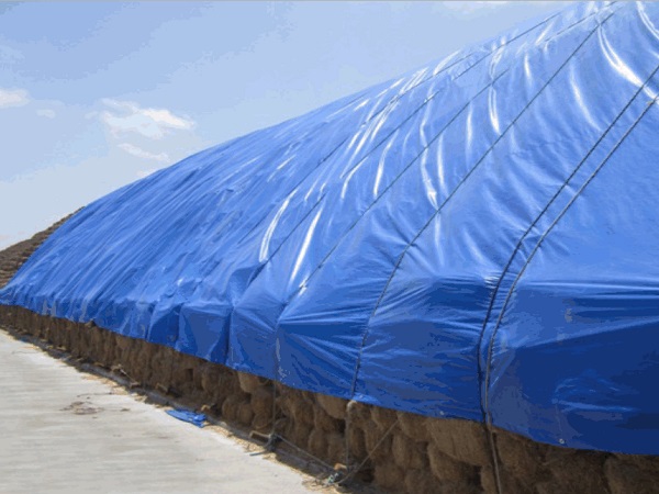
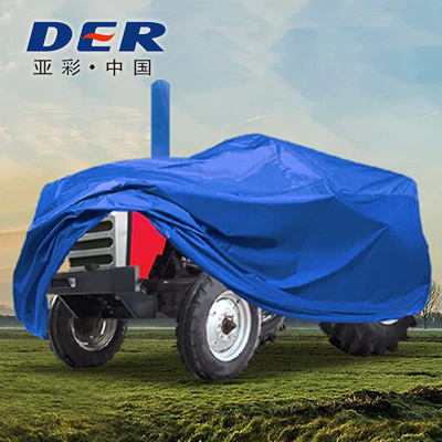
Imagine a stationary compressor with a tall service housing on one side and a pipe rising above its main roof. It would be inaccurate to choose a finished tarp only from its nominal base footprint. The right package would capture:
Overall length, width and total height in the actual parked condition.
Horizontal location of the height change and sloping transition length.
Pipe center, projection and whether it can safely be included or must remain open.
Door swing, cover-removal route, safe anchor points and required ventilation.
The proposed result might be a semi-fitted multi-panel cover, a simple draped cover with a separate weather hood, or a sectional enclosure. The choice depends on safety, operating state, use frequency and fabrication review—not on an arbitrary fixed clearance figure. Buyers protecting stored equipment can also review industrial storage tarp applications.
A production-ready inquiry links geometry to the material and service conditions. Include a labeled drawing and photos, the required finished cover behavior, and the intended quantity. There is no submission form on this page; the quote button opens the official DERFLEX request page.
For repeat programs, review an approved sample and agree how final dimensions will be checked before bulk fabrication. Explore made-to-measure tarpaulin programs.
Replace the bracketed fields. This brief is a starting point; your dimensioned drawing remains the fabrication reference.
PRODUCT: Custom industrial equipment tarp / fitted cover
EQUIPMENT: [type, model, parked configuration]
APPLICATION: [outdoor idle storage / other approved use]
DATUM: [origin location and X / Y / Z convention]
OVERALL ENVELOPE: L [ ] × W [ ] × H [ ] [units]
PROFILES: [station IDs, heights, slopes, curved paths]
PROTRUSIONS: [feature schedule + coordinate drawing]
ACCESS / SAFETY: [flaps, no-cover zones, ventilation]
FINISHED COVER: [desired fit, lower edge, functional drop]
FASTENINGS: [anchoring points, straps, eyelets, D-rings]
FABRIC: [preferred PVC specification, color, performance]
ORDER: [quantity, branding, packing, destination]
ATTACHMENTS: [drawing revision and labelled photos]
REQUEST: Confirm pattern, finished-size tolerance,
seam layout and sample approval before production.
You can also select and copy the text manually.
Practical answers for machine builders, importers, procurement managers and tarp fabricators specifying made-to-measure equipment covers.
Measure the maximum machine envelope in its covered condition, establish a fixed datum, then document profile stations, curved fabric paths, protrusions, openings and safe fixing points. Send top, side and detailed dimensioned views with labelled photos. The finished cover design is then reviewed against these measurements.
No. Those dimensions only describe the outer envelope. Raised housings, curved surfaces, projecting pipes, service doors, clearance and fastening locations can all change the cover pattern. A fitted cover needs the extra geometry recorded on a drawing.
Mark measurement stations and use a flexible tape to follow the route where the fabric must pass. Record the arc or slope path separately from the straight horizontal projection, and provide at least one cross-section that shows the profile.
There is no universal allowance. Required clearance depends on the projection, cover architecture, handling access, water shedding and any safety restrictions. Define the functional need and ask the fabricator to confirm the designed clearance and finished pattern. Hot exhaust and operating ventilation need separate technical review.
Specify the measured machine geometry and intended finished cover size or approved fitted pattern. The fabricator should calculate raw cut panels, seam overlap and hems based on the selected fabric and construction method. Agree the finished measurement condition and tolerance before approval.
Do not assume a standard PVC storage tarp can be used over operating equipment. Heat, exhaust, electrical access, cooling airflow and moving components may make a conventional cover unsafe. Follow the equipment manufacturer's directions and obtain an engineered operating enclosure where required.
Include front, rear, left, right and safe top-view photographs; detail images for marked projections and tie-downs; top and side dimension drawings with a datum and units; profile sections; and the quantity, service condition, material direction and required finished fit.
DERFLEX supports PVC coated fabric sourcing and custom tarp manufacturing discussions for OEMs, fabricators and industrial project buyers. Share the equipment geometry, marked photos, use conditions, quantity and target material so the team can review the practical cover construction before quoting.
Official DERFLEX quotation page. Materials and fabrication details are confirmed per project.