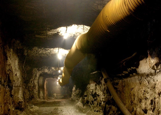
Underground Route Reality
Negative-pressure ducting has to stay open through suspension, bends, wall contact, fan connections and repeated route changes. Installation geometry should be treated as part of the product specification.



Shape-supported flexible ducting for mine and tunnel suction, localized exhaust and contaminated-air extraction where an unsupported layflat tube can collapse under vacuum.
DERFLEX can configure the PVC-coated textile body, continuous steel-wire helix or other support structure, wire pitch, section length, cuffs, suspension and optional wear protection around the fan duty and underground route. For a useful quotation, provide the airflow target, available negative static pressure, duct diameter or fan interface, route length, bends, installation method and any written flame or antistatic test requirement.
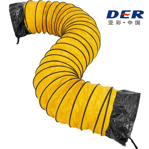
A plain layflat tube depends on positive internal pressure to stay inflated. Under suction, the wall can be pushed inward, so negative-pressure ventilation normally requires spiral wire, support rings or another shape-retaining structure sized for the actual vacuum, diameter and route.
The supporting wire is only one part of the design. Collapse resistance also depends on duct diameter, wall stiffness, wire gauge and pitch, bend geometry, local deformation, section length and the fan's operating point. This is why a specification such as “800 mm negative pressure mine duct” is incomplete without fan or pressure data.
For a wider system overview, see DERFLEX mining ventilation duct guidance, which separates forced-air, extraction and low-headroom duct architectures by operating duty.
Negative-pressure ducting has to stay open through suspension, bends, wall contact, fan connections and repeated route changes. Installation geometry should be treated as part of the product specification.
The purchase should be evaluated as a complete flexible air route rather than by fabric weight or diameter alone.
Polyester reinforcement carries mechanical load while the PVC-coated surfaces provide the flexible air barrier and weldable construction platform. Final weight, yarn structure and coating formulation are project-defined.
Continuous spiral support helps the round passage resist inward deformation under suction. Wire diameter and pitch should be reviewed together with duct diameter, wall stiffness and required negative pressure.
Welded or otherwise approved seams must be coordinated with the body construction so the assembled duct retains air containment and mechanical continuity during handling and operation.
Soft cuffs, rings, clamps, zippers, hook-and-loop interfaces or drawing-based adaptors can be matched to fans, existing duct lines and replacement sections.
Helix-supported hanging, loops, straps or dedicated reinforcement can be configured around the route. High-contact areas may need local wear strips or patches rather than a blanket increase in fabric weight.
Flame-retardant and antistatic configurations can be discussed when the mine or tunnel specification names the required test method, acceptance criteria and documentation. Performance should not be assumed from a generic label alone.
Closer or wider helix spacing changes support, flexibility, weight and packing behavior. The correct choice depends on the complete duct and operating condition.
Reducing unsupported wall span can improve local shape support, but exact negative-pressure capability must be verified for the full construction rather than inferred from pitch alone.
Pitch, wire gauge and wall stiffness influence how the duct follows corners. Very tight bends can ovalize the bore and increase system resistance even when the duct does not fully collapse.
More reinforcement can add weight and alter compressibility. Underground crews, hanging method, transport envelope and storage limits should therefore be considered before fixing the helix arrangement.
Use this table to align engineering, procurement and supplier quotations. DERFLEX should confirm final values on the approved product specification.
| RFQ Field | Project Direction | Why It Matters |
|---|---|---|
| Airflow mode | Negative pressure / suction / exhaust | Establishes that the duct must resist collapse rather than rely on internal inflation. |
| Fan / extractor data | Model, fan curve, target airflow and available static pressure where available | Defines the operating point that the duct route has to support. |
| Duct diameter | Project-defined from airflow, velocity, pressure loss, fan interface and clearance | Diameter affects friction, occupied space and required structural support. |
| Section length | Project-defined for handling, connection count and route extension | Longer sections reduce joint count but can be harder to carry, suspend and replace underground. |
| Body construction | PVC-coated polyester technical textile; exact structure by approved specification | Wall strength, flexibility, abrasion exposure and fabrication method all depend on the selected body. |
| Shape reinforcement | Continuous helix, support rings or another project-approved structure | Prevents or limits inward deformation when the fan creates suction. |
| Wire pitch / gauge | Confirm against diameter, negative pressure, bend radius and handling target | Changes collapse support, flexibility, weight and packed volume. |
| Connections | Soft cuff, ring, clamp, zipper, hook-and-loop or custom adaptor | Poorly matched interfaces add leakage, installation time and local stress. |
| Suspension | Helix support, straps, loops or project-defined hanging points | Sag, twisting and wall contact can reduce useful cross-section or create wear. |
| Wear protection | Optional strips, patches or cuff reinforcement at high-contact zones | Useful where ducting may rub rock, floor, equipment or fan frames. |
| Safety / test requirement | Named flame, antistatic, marking or documentation requirement | Allows the material and test plan to be aligned to the actual mine or project acceptance route. |
No universal vacuum rating, flame classification, antistatic value, MOQ or lead time is stated here because these fields depend on the final construction and confirmed project requirement.
The same reinforced duct concept can be configured differently depending on where suction is created and how the route is installed.
| Application | Structure to Evaluate | Key Inputs | Typical Procurement Risk |
|---|---|---|---|
| Localized dust or fume extraction in a mine heading | Spiral wire-reinforced round duct sized for suction duty | Required airflow, negative static pressure, route length, bend count, capture point and fan position | Ordering by diameter only and discovering that the wall deforms at the actual fan operating point. |
| Fan inlet or extractor connection | Short reinforced section with matched cuff, ring or custom adaptor | Fan flange/outlet drawing, clamp method, nearby obstructions and connection load | Field-made transition that leaks, twists or places excessive stress on the cuff. |
| Bend-heavy underground route | Helix-supported duct with pitch and bend geometry reviewed together | Minimum bend radius, route sketch, clearance and suspension points | Using a nominally flexible duct that kinks or becomes strongly oval through corners. |
| High-abrasion route near rock or mobile equipment | Reinforced duct with localized wear protection | Contact points, dragging frequency, suspension height and service access | Increasing total fabric weight while leaving the actual helix/contact zones unprotected. |
| Coal mine or safety-controlled underground project | Negative-pressure structure plus project-defined flame / antistatic configuration | Exact test method, acceptance criteria, report format and local approval requirement | Accepting a generic “FRAS” claim without matching the project's named test route. |
| Replacement or extension of an installed duct line | Matched section with replicated end interface, diameter and suspension geometry | Photos, measured cuff/ring dimensions, existing labels and connection sequence | Buying “the same diameter” but receiving sections that cannot connect to the installed system. |
Negative pressure mine ducting is selected when the ventilation system pulls air through the duct. The wall therefore needs shape support to resist inward collapse.
Positive pressure layflat ducting is selected when a fan pushes fresh air through the duct. Internal pressure inflates the flexible tube, allowing it to collapse flat for compact storage when the blower stops.
If the project is primarily fresh-air forcing rather than extraction, review DERFLEX blowing ventilation duct guidance instead of over-specifying a wire-supported suction duct.
| Decision | Negative Pressure Duct | Positive Pressure Layflat |
|---|---|---|
| Airflow direction | Suction / extraction | Blowing / supply |
| How the bore stays open | Helix, rings or other structural support | Internal positive pressure |
| Typical mining use | Localized exhaust, dust/fume removal, suction sections | Fresh-air delivery toward advancing headings |
| Transport profile | Compressible but reinforced | Very compact when unpressurized |
| Main selection risk | Insufficient collapse support at actual vacuum | Using unsupported layflat tube for suction duty |
For a round duct, a first-pass geometry check can relate airflow Q, average velocity v and cross-sectional area A:
A = Q / v and D = √(4Q / πv)
This only establishes a starting diameter. Final selection still has to consider fan curve, friction, negative static pressure, bend losses, joint leakage, partial deformation, route extension and underground clearance.
These errors create more project risk than small differences in nominal fabric weight or unit price.
Wire confirms that the duct has shape support; it does not by itself establish the allowable vacuum. Ask for confirmation against the complete construction and operating condition.
A layflat forcing duct and a negative-pressure suction duct solve different structural problems. Separate the airflow duty before comparing quotes.
A duct can remain generally open but still lose effective area through a tight bend. Include the route geometry and minimum bend radius in the RFQ.
The same diameter may face very different vacuum levels on different fans and routes. Fan data is essential for a meaningful support decision.
Provide fan interface drawings and existing coupling dimensions before production so cuffs, rings and adaptors can be built consistently.
Terms such as flame retardant or antistatic should be linked to the project’s named test method and documentation requirement rather than treated as universal approvals.
Final suitability depends on the complete ventilation plan, contaminant, fan duty and applicable project requirements.
Localized removal of contaminated air, dust or fumes from an advancing heading where the auxiliary ventilation plan uses suction rather than only fresh-air forcing.
Flexible extraction routes around temporary fans, access points and changing construction zones where rigid duct is difficult to relocate.
Shape-supported duct sections between a localized capture point and extractor, filter or ventilation line where the flexible wall must remain open under suction.
Short reinforced sections, bends or adaptors connecting fan inlets, equipment, rigid duct or different duct diameters.
Projects can use positive-pressure layflat supply duct and separate negative-pressure reinforced extraction duct. Each line should be specified independently.
Where headroom, vehicles or services constrain the duct envelope, the route may require smaller sections, shaped ducting or transitions after airflow and pressure-loss review.
DERFLEX can discuss a finished negative pressure ventilation duct as an assembly: coated textile body, wire reinforcement, fabrication, cuffs, suspension details, optional wear protection and project markings.
For mine-specific route planning, the underground mine ventilation duct page covers forced and exhausting layouts. Coal-mine projects should additionally define written flame and static-control requirements before production.
Where the project specifically requires documented safety treatments, review the antistatic flame-retardant mine ventilation duct configuration before finalizing the purchase specification.
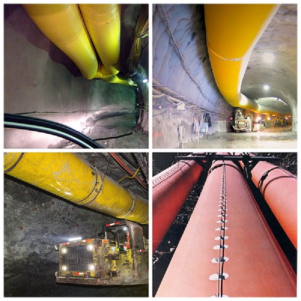
Real mine routes combine long suspended runs, reinforced sections, fan interfaces and changing underground geometry. Product drawings and site photos are useful RFQ inputs.
A complete enquiry reduces assumption-driven quotations and makes supplier comparisons more meaningful.
State suction / exhaust duty, target airflow, fan or extractor model and available negative static pressure or fan curve if available.
Provide target internal diameter, fan interface dimensions, total route length, preferred section length, bends, reducers and any low-clearance areas.
State suspended, floor-dragged, mobile or mixed use; include hanging method, spacing constraints and areas likely to contact rock or equipment.
Provide cuff, zipper, ring, clamp or existing mating-end details. Photos and measured dimensions are valuable for replacement projects.
Name the required flame, antistatic, marking, test report or approval route instead of using only broad labels such as “FRAS.”
Include quantity, delivery destination, phased supply plan, packaging needs and whether samples or a pre-production approval section are required.
These six verified DERFLEX pages support adjacent product, application and material decisions.
Direct answers for mine operators, ventilation engineers, EPC contractors, fan suppliers, distributors and procurement teams.
It is a flexible air-conveyance duct used where a fan or extractor pulls air through the line. Because suction can push an unsupported flexible wall inward, the duct normally uses spiral wire, support rings or another shape-retaining structure to keep the airflow passage open.
A negative pressure mine duct is commonly evaluated for localized exhaust, dust or fume extraction, fan inlet connections and mine or tunnel sections where contaminated air is being pulled away from a work zone rather than fresh air being forced toward it.
Unsupported layflat duct is normally intended for positive-pressure blowing because the fan inflates it. Under suction it can collapse. Negative-pressure service generally requires a spiral wire-reinforced, ring-supported or otherwise shape-retaining construction matched to the operating condition.
Wire pitch should be reviewed together with wire gauge, duct diameter, wall stiffness, required negative static pressure, bend radius, handling method and packing target. Tighter spacing can increase local support, but pitch alone is not a vacuum rating.
Start from required airflow and acceptable air velocity, then review fan curve, static pressure, route length, friction, bends, leakage, partial deformation and underground clearance. The final diameter should be confirmed as part of the complete ventilation system rather than copied from the fan outlet alone.
DERFLEX can discuss project-defined end connections, rings, clamps, cuffs, zippers, suspension details, wear strips, identification and other fabrication features. Final availability is confirmed against the approved project drawing or specification.
Project-specific flame-retardant and antistatic configurations can be discussed. The RFQ should state the exact test method, acceptance criteria and documentation required by the mine, contractor or local authority so the material and test plan can be aligned correctly.
Provide airflow direction, fan or extractor data, target airflow, available negative static pressure, duct diameter or fan interface, total run, section length, bend count, connections, suspension method, abrasion conditions, required test documents, quantity and destination.
Send DERFLEX your fan data, negative pressure, airflow target, route length, diameter, bend layout, coupling details, underground installation method and required safety documentation. The team can then review a suitable negative-pressure duct construction for sampling or quotation.