News
Company News

Drilling Fluid Containment Liner Fabric | DERFLEX

Update:2026/10/22 21:17:14 Views:
Skip to material guide

Oilfield service · Temporary capture · OEM fabric

Drilling Fluid Containment Liner Fabric for Oilfield Service

Develop a temporary capture liner around the mud it will actually meet. DERFLEX supplies coated fabrics for evaluation by drilling-service teams, pump-package OEMs and containment fabricators. Start with the complete fluid formulation, solids, contact temperature and cleanout method; then review the coating, reinforcement, welds and supported capture shape. Discuss roll material, usable width and sample requirements before approving a drilling fluid drip tray liner or a replacement service liner.

For controlled, temporary collection at service, coupling and transfer points. Compatibility is specific to the proposed fabric and exposure.

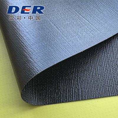
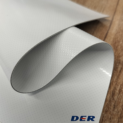
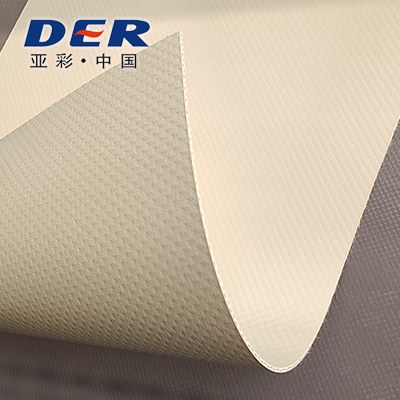
DERFLEX coated fabric swatches folded in a range of colors
Begin with the material. Qualify the assembly.Actual DERFLEX coated-fabric samples. Appearance and color do not establish drilling-mud resistance or identify an approved liner grade.
01 / Fluid identityWater, oil or synthetic base + additives
02 / Capture dutyDrips, service residue and controlled transfer
03 / Approval evidenceExposed fabric + welded prototype

Define the job first

What is drilling fluid containment liner fabric?

It is a coated textile evaluated for fabrication into a temporary, supported liquid-capture surface beneath a service point. A drilling mud spill liner material needs a liquid-contact coating, reinforcement for handling, and joints that retain their required performance after the expected mud and cleaning exposure.

The useful distinction is between covering equipment and holding released fluid. A weather cover specification does not establish a liquid-containment specification. See the separate oilfield equipment tarp and cover guide for external protection duties.

01 / Chemistry

Identify the complete drilling-fluid formulation

“Water-based,” “oil-based” and “synthetic-based” describe a starting point for review. None is a compatibility rating for a flexible liner.

Provide the supplier’s fluid designation, revision, SDS and relevant technical information, plus the working blend and plausible service contaminants. An SDS may not disclose every ingredient that matters to material selection; arrange a confidential technical exchange when the formulation cannot be shared openly. Include additives at their intended concentrations and any locally added treatment products.

Swipe horizontally to compare the fluid groups.

Fluid identity → information to provide → what to qualify
Fluid groupIdentify in the inquiryFocus of the exposure review
Water-based mudFresh water or brine; salts, pH range, polymers, lubricants, surfactants and other treatment products.Evaluate the working mixture and cleaning cycle. Water resistance does not establish tolerance of the complete mud.
Oil-based mudActual base oil, internal brine, oil/water ratio, emulsifier and wetting-agent packages; added solvents or contaminants.Review coating uptake, softening, extraction effects, adhesion and exposed seam strength. A lubricating-oil result cannot qualify the full emulsion.
Synthetic-based mudExact synthetic base-fluid product and chemistry, such as an olefin or ester system, together with the additive package.Assess each formulation individually. “Synthetic” and environmental product descriptions do not demonstrate compatibility with the liner.
Used or mixed residuesRepresentative field fluid, treatment history, solids and credible cross-contamination from servicing or transfer.Compare fresh and used mixtures when their compositions differ. Record a formulation range rather than approving an undefined waste stream.

This is a screening framework, not a DERFLEX resistance chart. SLB’s Drilling Fluid Basics provides background on fluid families and their liquid and solid components; it is not liner qualification evidence.

Keep the coating formulation in the discussion. A generic polymer chart or a rigid-PVC rating does not characterize a flexible coated textile, surface finish or weld. Review the chemical-contact specification for PVC coated fabric when preparing the material brief.

02 / Mechanical exposure

Map solids, abrasion and service temperature

A liner may survive liquid exposure yet lose its barrier where settled grit, a hose or a cleaning tool repeatedly rubs the coating.

A / RESIDUE

Describe the solids

State solids content and whether it is reported by mass or volume. Add particle-size information, angular cuttings, weighting materials, settled-bed depth and how long deposits remain before removal. Test slurry contact as well as the liquid phase where both affect the liner.

B / CONTACT

Locate the wear

Mark hose paths, pump feet, couplings, sharp edges, ground grit and tool movement. Keep equipment loads on suitable supports; the barrier layer needs protection from concentrated contact. Any wear pad or underlay also needs review for chemical contact and cleanout.

C / TEMPERATURE

Use capture-point values

Record the liquid temperature where it reaches the tray, its credible peak, ambient conditions and minimum folding temperature. Include rinse-water temperature and nearby hot surfaces. Downhole mud ratings do not define the conditions at a temporary service liner.

Define the full contact cycle

Specify the longest planned wet contact, delayed cleanout, repeated wet/dry exposure and storage after use. A short splash trial cannot establish performance during accumulated overnight residue or repeated cleaning.

Make removal part of the trial

Use the intended cleaning agent, dilution, brush or scraper, rinse and drying method. Inspect coating and joints after cleaning, then after folding and redeployment. Avoid treating aggressive cleaning as a solution to incompatible fluid exposure.

03 / Drawing review

Design temporary capture geometry and cleanout access

Show where the fluid can land, how it is retained, how it is removed and what keeps the walls upright. A flat sheet beneath a pump does not define a functioning capture tray.

Schematic of a supported temporary capture linerPlan view with a hose entering over a supported wall, a raised perimeter, a cleanout access area and a protected service zone. Section below separates the barrier from support and underlay. No dimensions or performance ratings are implied. PLAN / TEMPORARY SERVICE CAPTURE Protected service zone equipment supported separately Cleanoutaccess 010203 SECTION / SEPARATE THE FUNCTIONS Liquid-contact barrier + qualified joints Compatible protection layer / stable support beneath
Original schematic for discussion only. It is not a fabrication drawing, an approved containment design or a photograph of a supplied product. No dimensions or capacity are implied.
  1. Retain the corners and wallsShow the supporting frame or tray, attachment points and corner folds. Check wall shape with fluid present, hose movement and access in the actual arrangement; do not rely on unsupported fabric tension.
  2. Control the connection zoneLocate the coupling and spill footprint inside the capture area. Support hoses independently so their weight cannot pull a wall down. Any unavoidable penetration needs a qualified sealing detail and accessible inspection.
  3. Recover fluid and settled solidsAllow space for the approved removal tool or suction point. If a drain is required, specify the fitting, gasket, seal, closure and attached hose separately; assess clogging, movement and leakage at the complete interface.

For compact supported assemblies, compare the flexible spill tray and replaceable pallet-liner material guide. Broader floor and wall construction is covered in the containment berm fabric specification guide.

State required usable capture volume in the drawing brief. Nominal length × width × wall height is only a geometric envelope. Freeboard, wall deflection, equipment displacement, settled solids and the actual lowest retention edge affect usable volume. The system designer must establish capacity and operating limits for the intended incident.

04 / Material + fabrication

Evaluate coating, seams and corner retention

Specify the exposed face and finished joint. A GSM value or polymer family alone cannot establish drilling-fluid barrier performance.

PVC coated polyester and appropriate TPU coated-fabric constructions can enter a technical screening discussion. Neither family is approved for drilling mud by name. Select the candidate using the actual compound, coating distribution, reinforcement and exposure evidence; consider a different barrier system when these cannot meet the agreed criteria.

Swipe horizontally to compare the specification fields.

Specification fields to agree for an oilfield service containment fabric
ItemRecord in the specificationWhy it affects approval
Liquid-contact faceGrade reference, compound, finish and face identification; coating thickness or distribution where specified.Total fabric weight does not describe the thickness or behavior of the wetted coating.
Reinforcing textileConstruction; tensile and tear requirements in warp and weft; handling and fold requirements.The textile carries handling loads, but exposed scrim or cut edges can create liquid-entry paths.
Weight, thickness & widthAgreed nominal values, units, tolerances, measurement method and usable roll width.Compare handling, panel layout and weld allowance alongside barrier and strength performance.
Seam constructionWelding process, lap geometry, coated faces, seam position and grade-specific production trial.Weld behavior depends on the selected compound, finish and equipment. Do not use universal welding settings.
Corners & interfacesCorner joint detail, reinforcement, exposed-edge treatment and any drain or boot assembly.Multiple layers, folds and fittings can introduce leakage paths or concentrated peel loads.
Backing & wear protectionGround-contact face, support condition, compatible underlay and replaceable wear areas.Protection must remain in place and permit inspection without creating hidden contamination pockets.
Supply & identificationRoll quantity, face marking, lot reference, packing, drawing revision and required records.Repeat orders need the same approved construction and a traceable change process.

These are RFQ fields, not a stock-grade TDS. Material rolls are the starting supply discussion; quote scope must separately identify any cutting, welding or finished assembly. Frames, supports, drain hardware, installation and system engineering are not implied.

05 / Evidence before approval

Agree prototype and exposure acceptance criteria

Approve a documented material-and-assembly combination. Separate chemical exposure, retained mechanical properties and the capture performance of the fabricated tray.

  1. Freeze the test brief

    Identify fabric grade and lot, contact face, representative fluid revision, temperature, dwell, solids and cleaning procedure. Agree baseline methods, conditioning, specimen directions, acceptance limits and responsibilities before testing.

  2. Expose fabric and welded samples

    Include unexposed controls, the actual working mixture and cleaning products. Where phases can separate, review which separated phases may contact the liner. Include welds, corners or interface specimens rather than relying only on flat fabric.

  3. Inspect after service and cleaning

    Record surface changes, dimensions or mass where relevant, retained tensile and tear properties, coating adhesion and seam behavior. Distinguish the post-exposure state from the cleaned, dried and reconditioned state.

  4. Trial the supported prototype

    Use the intended support, hoses, recovery method and a defined test medium. Check leakage, wall retention, corner distortion, cleanout and redeployment. Changes to the approved fluid, coating, weld or geometry trigger a review of the affected evidence.

Swipe horizontally to compare the acceptance criteria.

Define acceptance before testing — project limits are to be agreed
EvaluationDocument the observation or resultAcceptance decision
Coating conditionSoftening, tack, swelling, cracking, blistering, delamination and changes after cleaning.Set permitted changes and rejection conditions for the actual handling and barrier duty.
Retained propertiesBaseline and exposed tensile, tear, adhesion and seam results using consistent methods and directions.Define both a minimum residual value and retention criterion where appropriate. A retention percentage alone may hide inadequate starting strength.
Assembly leakageTest medium, fill level, duration, support geometry, inspected interfaces and detectable leakage.State the leakage criterion, inspection method and test conditions; do not infer chemical permeation from a water-fill check.
Cleanout & reuseResidue removal, coating and corner condition, fold damage and repeat-deployment observations.Agree the service cycle, inspection access, repair assessment and retirement triggers.

Method references: ISO 6450:2021 addresses liquid-exposure assessment of coated fabrics. ASTM D751-26 covers multiple coated-fabric tests. The laboratory must select applicable procedures and a project-specific exposure plan. Naming these standards does not state that a DERFLEX grade has passed them.

Have a fluid sheet and a tray sketch?
Use them to define the sample, fabrication trial and documents needed.

Discuss a Sample Evaluation ↗

Before you order

Resolve the service details that change the specification

Drawing and operating notes

  • Measure the supported interior. Include corner radii, wall height, seam allowances, hold-down details and access clearances.
  • Mark every interruption. Show hoses, penetrations, drain fittings and nearby supports; provide a separate detail for each seal.
  • Plan removal. Avoid lifting or dragging a liner full of slurry unless the complete assembly has been designed and validated for that duty.
  • Set inspection access. Keep joints, wear areas and the underside accessible for checks before use and after cleanout.

Procurement and reuse notes

  • Ask for the grade-specific document. A general coated-fabric brochure does not replace a TDS linked to the offered construction and available exposure evidence.
  • Approve a representative prototype. Use the intended welding equipment, joint details, support and cleaning method before repeat fabrication.
  • Quarantine damaged liners. Leaks, exposed reinforcement, persistent tack, cracking or joint separation require assessment before reuse.
  • Define the commercial scope. Material, usable width and cutting yield, seam work, quantity, packing and destination affect quotations. Confirm MOQ, lead time and terms for the proposed order.

Different containment task? Long-term mud ponds, tailings storage and heap-leach facilities require a separately engineered lining system, installation controls and project-specific evidence. Start a separate review through the geomembrane and engineered containment membrane range; this temporary service-liner guide does not qualify those applications.

Turn the service brief into a material inquiry

Share fluid chemistry, solids content and temporary capture details.

Send your mud designation, a sketch of the capture arrangement and the expected service cycle. DERFLEX can start a coated-fabric discussion around the liquid-contact face, reinforcement, roll format and sample evaluation requirements.

For confidential formulations, begin with the fluid family, supplier product code and technical contact. Arrange the appropriate confidentiality process before sending restricted formulation data.

Use the existing inquiry page to request the relevant TDS, available liquid-exposure information and a quotation scope. No unverified test report or generic chemical rating is offered as proof.

Related questions

Drilling-fluid liner fabric FAQ

Can one liner grade cover water-, oil- and synthetic-based mud?

Only if evidence covers each defined formulation and its contact conditions. Passing one water-based mixture does not qualify an oil-based emulsion or an ester-based synthetic fluid. Additives, contamination, temperature and cleaning can change the assessment.

Which GSM or thickness should I specify?

Begin with the required barrier, handling and assembly performance. Compare contact-side coating, reinforcement, usable width and weld behavior as well as mass and thickness. There is no universal GSM that qualifies a drilling fluid drip tray liner, and GSM cannot be converted directly into thickness without construction and density information.

Is an SDS enough to select a drilling mud spill liner material?

An SDS is useful for identification and handling, but may not disclose the full formulation needed for compatibility review. Provide the working blend, treatment products, actual temperature, contact time and solids. Confidential technical exchange or representative-fluid testing may be needed.

Why test seams and corners after fluid exposure?

Flat fabric does not reproduce a welded overlap, folded corner or drain interface. Chemical contact and cleaning can affect the coating and joint differently. Test relevant fabricated details, then check the supported prototype for leakage, wall retention and cleanout access.

Can a water-fill test prove drilling-fluid resistance?

No. A water-fill check can assess leakage of an assembly under specified conditions. It does not establish resistance to the mud chemistry, retained strength after exposure or chemical permeation. Those questions need their own methods and acceptance criteria.

Does this fabric replace a mud-pit or tailings liner?

No such substitution is established by this page. Temporary capture at a maintenance or transfer point is a different duty from a long-term pond, tailings facility or heap-leach pad. Those projects need a separately specified and engineered lining system.

Technical context: external references on this page explain fluid classification and test-method scope. They do not certify a material, a fabricated tray or an operating system. Approval must identify the actual fluid, fabric, seams and service conditions.

Consulting Services
+86-021-54361792 / 54361798
Email
sales@derflex.com