


 Coated fabrics / custom cover planning
Modular Tarp Panels: Designing Large Covers for Easier Handling and Replacement
Modular tarp panels divide a large cover into identified sections for planned opening, handling and replacement. The design must coordinate panel size, overlap, connectors and reinforcement. Use this guide to estimate fabric mass, compare removable joints and define repeatable interfaces for OEM and industrial cover programs. Discuss PVC-coated fabric rolls, pre-cut pieces or fabricated panels with DERFLEX against an approved drawing, including the proposed joint and exact supply scope.

Set its finished geometry, orientation and mating edges.
Design load transfer and rain protection as distinct requirements.
Retain the interface drawing, panel ID and revision.
Divide the handling task, then design the joint.
A sectional cover is useful only if its parts can be installed, opened and replaced in the intended working space.
Modular tarp panels are separately identified cover sections designed to function together. True replacement modules need a defined way to disconnect. Several strips permanently welded into one large sheet are fabrication panels, not automatically detachable sections.
| Decision | One-piece cover | Modular cover |
|---|---|---|
| Handling & access | Fewer field connections; the full sheet must be moved or opened. | Smaller individual sections; more connections to assemble and inspect. |
| Rain protection | Fewer removable interfaces to detail. Fabrication seams still require verification. | Each removable interface needs an agreed overlap, flap, support and drainage arrangement. |
| Local damage | May need a patch or substantial workshop rework. | A defined section can be replaced if mating edges and adjacent fabric remain serviceable. |
| Ownership cost | Less interface hardware and overlap material. | Additional finishing, identification, assembly time and spares; compare these against the actual maintenance task. |
A pre-cut blank is a supply stage, not a complete connection design. Review pre-cut tarp panels and blanks when your workshop will finish the edges locally.
Choose the module around access, not an arbitrary size.
Map the cover surface, support lines, runoff, abrasion zones and the route for removing a middle panel. Position a connection where it can be reached and inspected, rather than over an unsupported low point.
Measure over the profile.
Separate ground footprint from the developed cover surface. Include side drops, corners, protrusions and required access; a curved profile needs more than its plan width.
Test a middle-panel change.
Check whether adjoining panels must be released and whether rails or end stops prevent extraction. A smaller panel still needs a practical removal path.
Calculate net coverage.
For equal rectangular panels in one row: assembled run = panel count × panel run − total overlap. Keep cut allowances, finished size and net coverage separate.
Estimate a rectangular panel layout.
Equal panels, one row of overlaps, flat geometry. The cross dimension is the developed cover dimension, including any planned drop. This does not determine roll width, fabrication seams or a safe handling limit.
3 panels · 2 joints · 65.52 kg combined fabric estimate.
Formula: panel run = [assembled run + (panel count − 1) × overlap] ÷ panel count. Fabric mass (kg) = rectangular area (m²) × GSM ÷ 1,000. Excludes extra fabric for hems, flaps and reinforcement, hardware, packaging, moisture and waste. Inputs are illustrative, not a DERFLEX stock specification.
Worked example: less mass per piece, more total fabric.
At an illustrative 650 g/m², a 12 × 8 m rectangle contains 62.40 kg of fabric. Three 4.2 × 8 m rectangles with two 0.3 m overlaps cover the same 12 m run: 21.84 kg per piece, 65.52 kg in total. The overlaps add 4.8 m² of fabric before finishing. This is a geometry example, not a lifting recommendation or a cost-saving claim.
GSM describes mass per area, not tear strength, seam strength or stiffness. Choose the construction using PVC tarpaulin material options and the actual service conditions.
Specify the load path and the rain path separately.
A connector holds parts together; a rain flap manages exposure at the opening. One detail does not automatically perform both jobs.
| Interface | Useful design role | What to resolve |
|---|---|---|
| Lacing or straps with a cover flap | Detachable connection between reinforced panel edges. | Edge loading, hole or strap positions, abrasion, access to tensioning and a retained weather-facing flap. Exposed holes can admit rain. |
| Separating zipper | Repeated removal or an access section where the complete zipper type permits separation. | Handedness, start and stop positions, pull access, compatible mating halves and separate restraint where required. Do not assume an ordinary access zipper detaches a whole panel. |
| Hook-and-loop flap | Convenient flap retention or an access closure. | Peel loading, dirt, engagement and weather aging. It is not automatically the primary restraint for a large exposed cover. |
| Keder edge in a rail | Panel-to-frame interface using a matched bead and track. | Profile fit, rail condition, insertion direction, end access and release sequence. This is not a universal fabric-to-fabric joint; confirm hardware scope separately. |
| Permanent welded join | Joining compatible material within a module or a continuous sheet. | Process qualification and seam acceptance. Replacing that section requires cutting and qualified rejoining; it is not a tool-free detachable joint. |
Keep runoff outside the connection.
Draw which panel laps over the next, how the flap is retained and where water exits. Avoid a joint that creates a gutter or terminates at an unprotected corner. Ponding and wind-driven rain require separate attention.
Use the welded versus sewn seam guide to distinguish joint strength from resistance to leakage.
Make removal a controlled operation.
Show the temporary support and release sequence before loosening a loaded interface. Do not open a tensioned connection or treat a flap as a lifting point. Confirm installation conditions and site procedures with the responsible operator.
For frequent access, compare zippered tarp openings and detachable closures.
Put the replaceable section where maintenance happens.
Use the same interface discipline across applications, while changing the panel layout to suit the support, opening cycle and exposure.
| Application | Layout priority | Verify before approval |
|---|---|---|
| Bulk material stockpiles | Separate frequently opened zones from longer-term coverage. | Changing pile profile, ground abrasion, drainage, anchoring and the actual deployment method. See industrial stockpile covers. |
| Equipment protection | Isolate service-access panels and parts exposed to repeated contact. | Hot surfaces, sharp protrusions, condensation, clearance and attachment to approved points. |
| Temporary building enclosure | Coordinate modules with bays, openings and planned work access. | Structural supports, wind actions, edge restraint and applicable project requirements. Review building enclosure tarp panels. |
| Existing rail or rolling cover | Match a named system and its extraction path. | Rail profile, stops, curve geometry and system-owner requirements. A generic same-size panel may not fit. |

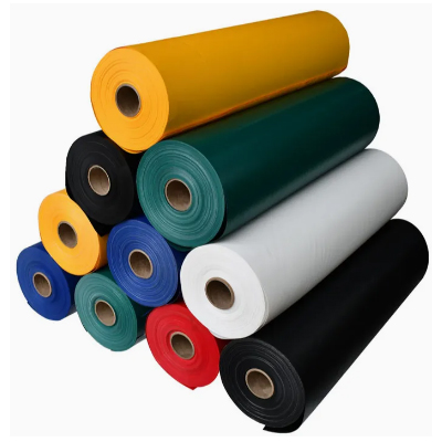

A replacement panel needs an interface record.
Matching width and length is only the beginning. Identify the cover set, the exact position and the features that must mate with neighboring sections.
| Control | Record on the approved specification |
|---|---|
| Identity & orientation | Cover-set ID, P01/P02/P03 position, drawing revision, outward face, top and runoff arrow; define the viewpoint for left and right. |
| Geometry & datums | Finished dimensions and tolerances under an agreed measurement condition; named reference corner; diagonals, drops, pockets and cut-outs where applicable. Assign responsibility for cut and finishing allowances. |
| Mating edges | J1A/J1B and J2A/J2B edge IDs, connector type, pitch, first and last positions, edge offsets, mating orientation and weather-flap ownership. Locate features from a common datum to control cumulative mismatch. |
| Material & reinforcement | Approved fabric reference, face and warp/weft direction, GSM and gauge if required, coating, color, seam locations, wear patches and edge construction. Agree evidence for any claimed environmental or fire performance. |
| Supply & kit contents | Raw blanks, partially finished panels or completed sections; quantity per ID; included connectors and spares; packing sequence and labels. Separately list rails, supports, tools and installation responsibilities. |
| Acceptance & retention | Dimensional checks, mating-fit trial, relevant seam and attachment checks, agreed leakage test, inspection sampling and the records retained for repeat orders. |
Replacement compatibility needs confirmation. UV exposure, dirt, material distortion, discontinued connectors and changes to the frame can affect a later fit. Agree spare quantities and record retention at the start; do not assume indefinite availability or an exact color match to aged fabric.
DERFLEX’s tarp RFQ and acceptance specification pack provides a broader starting point for material, fabrication and inspection requirements.
Approve the interface before the complete cover set.
Start with photographs, a sketch and the intended opening sequence. The next step is a coordinated drawing and representative sample, rather than a quote based only on total square metres.
- Define the duty and scope. State indoor or outdoor use, support arrangement, rain exposure, cleaning, contact surfaces and handling frequency. Select material rolls, blanks or fabricated panels. Structural design, anchoring, rail hardware and site installation must be expressly allocated.
- Trial the difficult connection. Approve a mating pair that includes the real material, reinforcement, connector and flap termination. Check closure access and loading direction; verify strength and leakage separately against agreed requirements.
- Check a first assembly. Confirm installed coverage, middle-panel removal, aligned fasteners, drainage and the agreed finished dimensions. A connector coupon alone does not establish full-cover fit or weather performance.
- Plan inspection and packing. Inspect seams, skipped or misaligned fittings and label orientation. Pack by panel ID and assembly order; protect connectors and include an agreed panel schedule with the shipment.
Handling and storage notes
Assess wind exposure, reach, footing, wet weight and available equipment as well as panel mass. Keep dragging and sharp folds away from connectors. Clean, dry and pack sections so their identity remains readable.
What changes the quotation?
Material grade, usable roll width, number of fabrication seams, detachable-joint length, hardware count, reinforcement, trial assemblies, spare quantities and packing. Smaller modules do not automatically cost less overall.
Modular tarp panel FAQ
What are modular tarp panels?
Modular tarp panels are separately identified cover sections designed to work together as one cover. A removable connection allows a section to be detached; permanently welded fabrication strips do not become replaceable modules just because the cover contains several pieces.
Are modular tarp connections waterproof?
Waterproof fabric alone does not make a removable connection waterproof. Overlap direction, rain-flap retention, penetrations, support and drainage all affect leakage. Agree the required exposure and verify a representative assembled joint before approving production.
How large should each tarp panel be?
Start with access, handling equipment, deployment conditions and the proposed joint layout. Estimate fabric mass from area and GSM, then include hems, reinforcement and hardware. There is no universal safe panel size or crew count based on GSM alone.
Can a new panel fit an existing large cover?
Only after its mating edges are verified. Record the existing drawing revision, finished geometry, hardware positions, closure orientation and adjacent material condition. An aged or distorted cover may need a measured sample or trial fit rather than a copy of its original nominal size.
Is a modular tarp always better than a one-piece cover?
No. A one-piece cover avoids field connections and may suit infrequent removal where handling is practical. Modular construction is useful when local access or individual replacement justifies additional joints, overlap material, inspection and assembly work.
What information is needed to reorder one replacement section?
Provide the cover-set ID, panel ID, drawing revision, orientation, finished dimensions and mating-edge schedule. Add current photographs and identify any changes to the support or neighboring panels. Agree the replacement specification and fit check before manufacture.
Send the layout. Identify the section that needs to open.
Share the overall developed dimensions, support or equipment photos, intended panel count, opening frequency, environment, quantity and destination. For replacements, add the existing panel ID, drawing revision and close-ups of both mating edges.
DERFLEX can review the material and fabrication request, proposed interfaces, sample needs and exact quotation scope with you.
DERFLEX · Modular tarp panel design guide · Updated 24 October 2026