


 TECHNICAL PROCUREMENT GUIDE
Spill Tray Seam & Corner Integrity After Chemical Exposure
A coated fabric that withstands a liquid does not automatically prove that its welded seam or three-dimensional tray corner will remain sound. For flexible spill-tray OEMs, a defensible qualification plan compares matched parent-fabric and production-weld samples before and after contact, records the way each joint fails, and checks a representative floor-to-wall assembly for leakage. Define the actual liquid, exposure cycle, joining method and pass/fail limits before sampling—not after a leak appears.
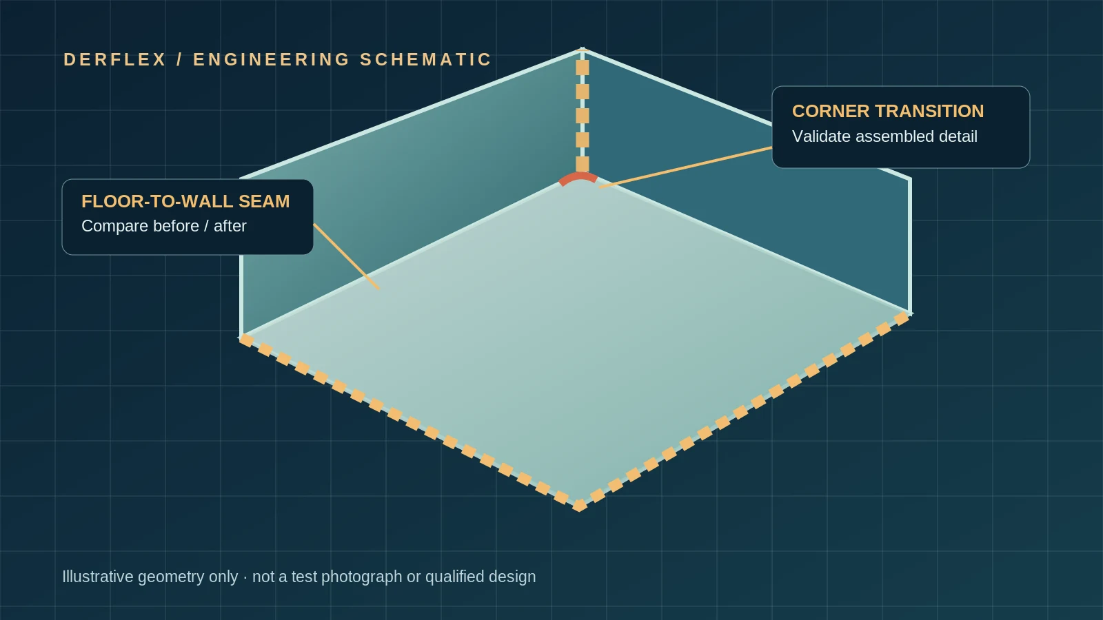
Select floor-to-wall and real corner specimens
Match the supplied material to the intended conversion process. Flat swatches answer material questions; production seams and shaped corner assemblies answer different, equally important questions.
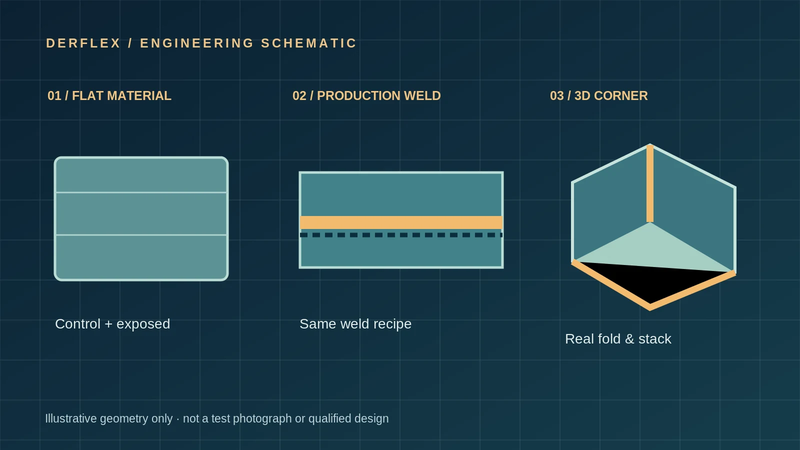
Qualify three levels together: the parent fabric, a straight seam made with the production recipe, and the actual multi-layer corner detail. Keep untreated controls from the same batch and label which coated face was exposed.
Parent fabric
Same roll and coating face, with unexposed controls and exposed specimens. Track visible change, dimensional behavior and appropriate mechanical properties in stated directions.
Welded lap coupon
Use actual overlap, weld-face orientation, tooling and settings. Prepare matched coupons for seam load, peel behavior and failure-mode comparison as appropriate.
Corner & floor junction
Reproduce folds, layer steps, terminations, patch intersections and wall attachment in the same arrangement used by the OEM tray or berm.
If a drain or fitting pierces the liner, give it its own representative specimen. The containment liner drain and penetration guide addresses details that straight-weld results cannot cover.
Record the welding window and contact-side finish
A chemical-exposure result is meaningful only when the welded sample can be traced back to the process that the factory intends to repeat. Nominal machine temperature alone is not a complete weld record.
| Record | Minimum information to retain |
|---|---|
| Material identity | Supplier grade, roll/batch ID, nominal construction, coated sides and surface finish. |
| Joint geometry | Lap/edge detail, weld width, actual overlap, fabric direction, number of layers and corner radius or fold detail. |
| Equipment & method | Hot-air, hot-wedge or RF/HF welding, machine/fixture identity, tooling and maintenance/calibration reference as relevant. |
| Window settings | Setpoint and any measured tool temperature, speed or dwell, pressure/force, energy/power and operating conditions as applicable. |
| Surface preparation | Contact-facing side, cleaning, pre-treatment, handling, weld-zone contamination checks and cooling/conditioning time. |
| Inspection identity | Operator, production date, shift, coupon ID, photo with scale and traceable data/report ID. |
Keep chemistry from becoming a hidden weld variable
A topcoat, textured finish, coating thickness or cleaner used at the lap interface may affect fusion. Before any liquid contact, document the exact faces being joined and whether the finished production wall exposes the same surface as the lab coupon.
For background on the broader flexible spill tray liner material, choose the grade and floor detail first; then qualify that grade with the planned welding process.
Matching GSM or color does not establish an equivalent bonding window across grades, coating finishes, machine types or fabric batches.
Compare retained seam performance after exposure
Set up a controlled, paired before/after program for the exact fluid or mixture. Log both measured load and the location where separation begins; the same peak value can reflect different failure mechanisms.
Exact commercial grade or SDS, blend/additives, concentration and credible co-contaminants.
Liquid face, temperature, period, total or one-face contact and cleaning cycle.
As-exposed or cleaned/dried specimens; record elapsed time and test environment.
Same method, width, loading configuration and units; preserve each individual result.
The retention value is informative only for matched specimen geometry, width, test rate, conditioning, loading mode and reporting units. State sample count and variability; do not hide a single low result inside an average. Agree minimum absolute strength, retention, failure modes and leak criteria with the OEM before tests begin.
Use coated fabric liquid-resistance testing to design parent-material exposure, including ISO 6450:2021 Method A (total immersion) or Method B (one-surface contact) where applicable. It is not a finished seam or tray certification.
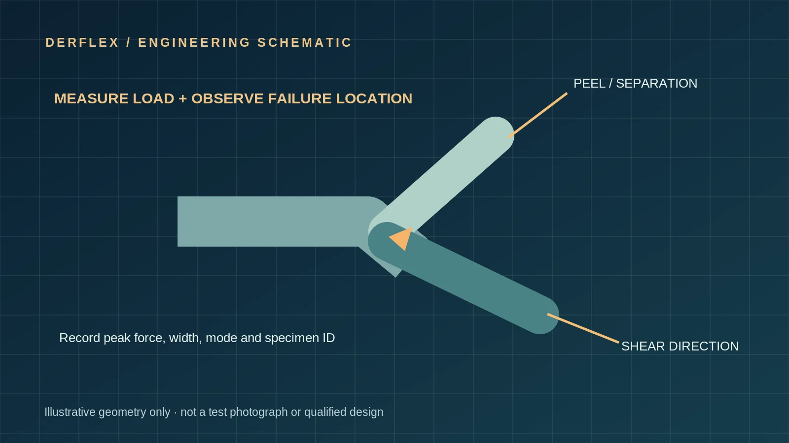
Failure-mode interpretation must accompany the measured force
Separation follows the joining interface. Investigate fusion/contact, finish compatibility, contamination and local pressure at the overlap.
The textile/coating interface releases. Compare with unexposed controls and coating-adhesion results; do not assume a stronger weld when the coating itself has degraded.
Crack or tear develops away from the initial interface. Record its position and direction; compare with the parent-fabric response and load geometry.
Multiple modes, stacked layers or a fold-root crack may govern the tray even when flat straight coupons appear satisfactory.
ASTM D751 includes coated-fabric seam-strength procedures; specify the selected procedure and any additional peel arrangement. ASTM D6392 concerns nonreinforced geomembrane thermal seams and must not be claimed as automatically valid for reinforced woven coated fabric. Actual fuel contact may need extra controls beyond a general liquid-immersion method. Review fuel blend compatibility before grouping diesel, biodiesel and gasoline into one test category.
Separate leak checks from strength measurements
Destructive peel or seam-load tests do not prove the assembled basin is free from leakage. Conversely, a prototype that holds water for a defined period has not proved long-term fuel barrier performance.
Record force, specimen width, separation mode, conditioning and whether a joint or parent material failed.
On a supported assembled tray, define fill level, hold duration, substrate, corner access and an explicit detection criterion.
Check affected material, seams and corner details using the actual liquid under approved controlled conditions.
Document cleaning, fold/deploy cycling, visual defects and criteria for repair, retest or removal from service.
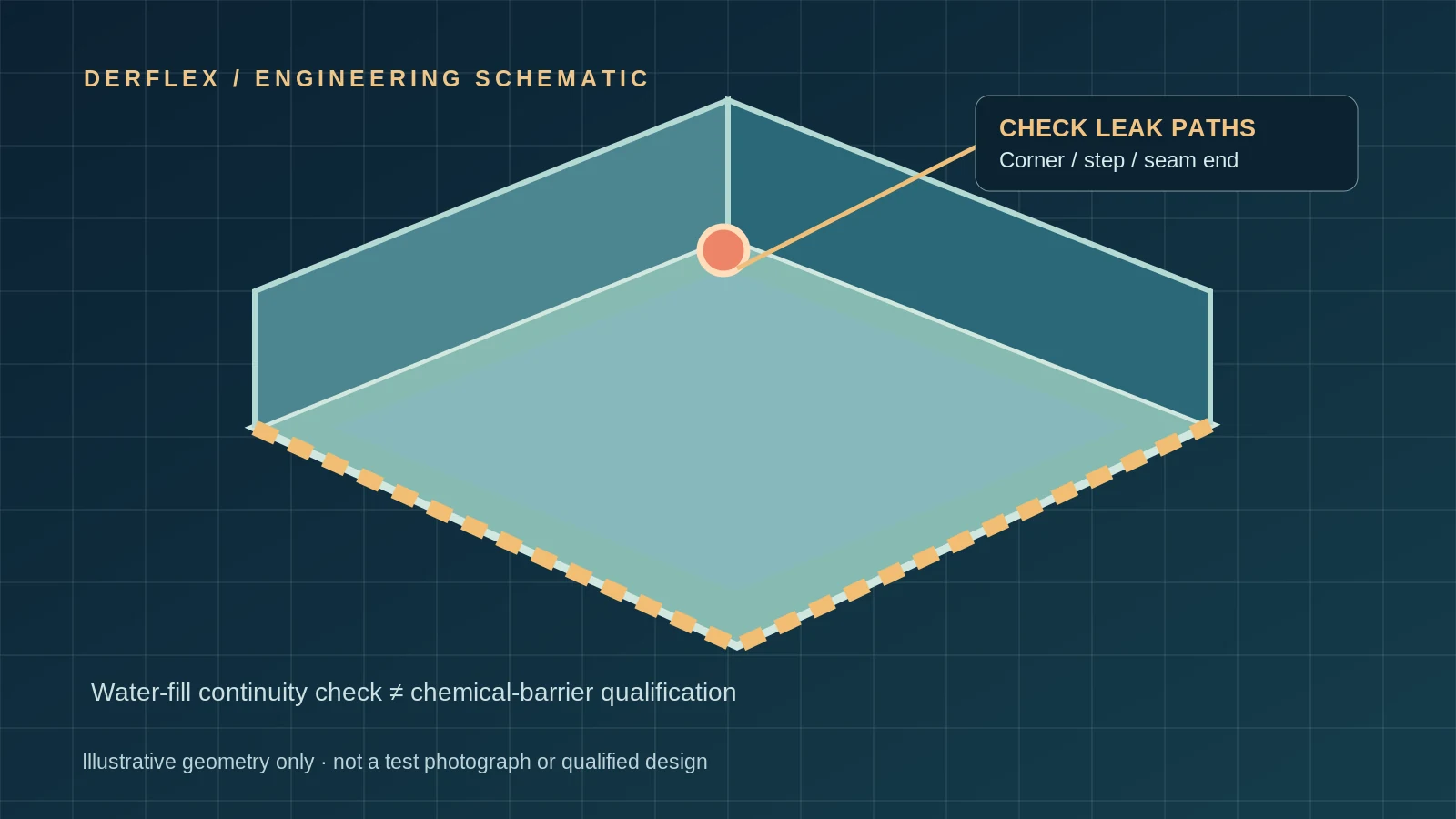
Passing a water-hold test establishes only that no leakage was detected under its stated conditions. It does not prove resistance to gasoline, biodiesel, mixed solvents, permeation or loss of mechanical properties after chemical exposure.
Approve the prototype assembly and production controls
Make sign-off a documented system decision: an approved material alone, a passing weld coupon alone or an initial water check alone is insufficient for the intended chemical containment duty.
Verified material identity, matching coated faces, supply tolerances and actual-liquid contact evidence.
Approved joint geometry, operating window, operator/fixture controls and baseline seam results.
Individual load values, retention calculation, observed failure modes and agreed acceptance limits.
Representative tray/corner under declared support, fill condition and hold duration, with observed result and photos.
Retest when grade, finish, relevant additives, weld tooling, corner design or critical exposure duty changes.
Traceable weld logs, representative quality samples, visible inspection, repair rules and reuse/retirement criteria.
Buyer-ready evidence pack
| Evidence | What a useful record contains |
|---|---|
| Exposure matrix | Liquid identity and batch, contact face, concentration/blend, time, temperature and cleaning state. |
| Control pairs | Fabric and weld coupon identifiers tied to the same lot and production recipe. |
| Raw measurements | Individual force, width, units, method, specimen direction, failure mode and date. |
| Comparative evaluation | Control/exposed comparison, calculation basis, observed scatter and pre-agreed criteria. |
| Corner / tray evidence | Dimensioned corner drawing, inspection photos, leak-check procedure and recorded observations. |
| Release decision | Approval authority, deviations, limitations and requalification triggers. |
This is a reporting framework, not a claim of existing DERFLEX laboratory results or a downloadable certified TDS.
Before you order or approve
- Send a dimensioned seam/corner drawing, not only the finished tray outside dimensions.
- Identify the intended liquid side, actual product grade and finished coating or topcoat.
- Describe each chemical and cleaner; include the SDS where available.
- State contact period, temperatures, number of reuse and folding cycles.
- Define the OEM's acceptance limits and who will conduct the tests.
- Confirm whether supply is coated roll goods, conversion samples or an assembled tray; these are distinct scopes.
Use the containment fabric TDS specification guide to align the material grade and batch evidence, and the spill containment berm fabric guide for roll-material selection and fabrication boundaries.
Use standards within their actual scope
The references below guide method selection; they do not certify a DERFLEX product, a conversion process or the assembled tray. Confirm the latest official editions and laboratory procedures before placing them in an order specification.
Coated-fabric properties before and after total or one-sided liquid exposure; not a full-assembly leak method.
Test-method family includes seam strength and material properties. Specify actual procedure and specimen details.
Questions engineers ask before approving a spill-tray seam
Direct answers for flexible tray manufacturers, welders, OEM development teams and supplier quality engineers.
Does a passing water leak test prove resistance to diesel or gasoline?
No. A water-fill check assesses leakage under its stated level, duration and support conditions. It cannot establish chemical compatibility, permeation resistance or retained weld strength after fuel exposure.
What should be tested in addition to flat coated fabric?
Use matched production-weld coupons and full-size or representative floor-to-wall and corner details. These capture overlap interfaces, material stacks, folds and changes in weld pressure that a flat fabric specimen cannot reproduce.
How is retained seam strength calculated?
When the same method, specimen geometry, width, conditioning and units are used, retained strength (%) = mean strength after exposure ÷ mean unexposed control strength × 100. Report the individual values and failure modes; agree acceptance limits before testing.
Can an ASTM geomembrane seam method be applied to reinforced coated fabric?
Not automatically. ASTM D6392 is written for nonreinforced geomembrane seams. A reinforced coated-fabric program needs a method appropriate to its construction and the intended load mode, with any adapted procedure clearly documented.
Why test actual corners instead of only straight welds?
Corners can contain overlapping layers, fold memory, thickness steps and seam terminations. These can create capillary paths or local stresses even when a straight-lap specimen meets a mechanical acceptance requirement.
What must an OEM send for a useful test plan?
Send the tray drawing and corner detail, fabric grade or sample, welding process and recorded settings, exact contact liquid or SDS, exposure duration and temperature, cleaning cycle and intended reuse conditions.
Send your seam drawing, welding process and contact liquid.
Share a corner drawing, fabric construction, machine method, fluid/SDS and expected exposure cycle. Request a material and test-plan discussion for your OEM tray or berm program. DERFLEX material supply and fabricator testing responsibilities will be confirmed by project.