Parallel to the original selvage
Warp yarns extend along the fabric as it is woven. For a conventional woven roll, this is normally the length being unwound. A panel's long side is warp only if the cutting pattern places it that way.



A tarp panel has two yarn directions, even when its PVC surface looks uniform. Rotating the cutting pattern can change which direction carries the main tension, how the panel extends and how adjoining panels behave.
For fabricators, OEM cover brands and industrial buyers, this guide connects warp and weft to a practical cutting plan. DERFLEX supplies PVC coated polyester fabric and custom tarps with project-based size, seam and reinforcement options. Send your drawing and service conditions to discuss material selection and sample validation.
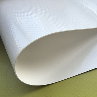
Warp yarns run lengthwise in woven fabric, parallel to its original selvage; weft yarns run across it. In a conventional full-width woven tarp roll, these usually correspond to roll length and roll width. Cutting direction matters because the two axes can have different tensile strength and extension. Choose orientation from the actual material data and load path; warp is not automatically the stronger direction.
In woven PVC tarpaulin, the polyester base fabric supplies much of the load-carrying structure. The coating provides a protective surface and interacts with that structure. Yarn size, yarn count, weave crimp and processing can produce different responses along each axis.
Warp yarns extend along the fabric as it is woven. For a conventional woven roll, this is normally the length being unwound. A panel's long side is warp only if the cutting pattern places it that way.
Weft yarns interlace across the warp. Turning a rectangular pattern through 90° exchanges the warp and weft assignments of its two sides, without changing its nominal dimensions.
A 45° direction is the usual bias reference. Off-axis loading can involve yarn rotation and shear. Do not assume a bias panel retains either on-axis tensile result or the same fit behavior.
A trimmed or slit edge may not be an original selvage. A rewound, cross-cut or assembled sheet can obscure the original fabric orientation. MD and CD describe manufacturing directions and need confirmation against the yarn axes.
Unreinforced film has no woven warp or weft. Knitted reinforcement and nonwoven constructions also need their own direction convention; do not assign woven terminology from appearance.
Place the material axis that meets the required strength and deformation limits along the critical load path, then check the transverse direction, seams and attachments. The longest cover dimension is not automatically the most heavily loaded direction.
| Application | Orientation decision | Evidence to request |
|---|---|---|
| Frame-supported cover with a dominant span | Identify which yarn axis crosses the critical span and transfers tension to the supports. | Both tensile directions, extension at agreed loads, support layout and seam position. |
| Truck side curtain or strapped cover | Map the load between rails, straps and buckles. Include local hardware zones and repeated handling. | Panel orientation drawing, seam tests and representative attachment pull tests. |
| Tent roof or tensioned membrane | Follow the engineered panel pattern and compensation plan. A heavier roll does not justify rotating approved panels. | Relevant biaxial material behavior, project design data and fabricated seam validation. |
| Custom machine cover | Balance fit, handling and repeatable panel alignment; check local tension near straps and corners. | Direction-marked prototype, finished dimensions and a trial on the actual equipment. |
| Flat cover pulled from several edges | Set requirements for both axes because a single dominant direction may not exist. | Two-direction tensile and tear data, attachment layout and installed fit. |
| Small reinforcement patch | Evaluate the patch axes against the force entering the parent panel; specify permitted rotation. | Patch drawing plus seam or attachment tests on the complete reinforced detail. |
A strong panel can still extend enough at service load to lose its intended shape. Elongation at break describes the end of a test; it is not the extension expected during use. Where fit matters, request extension at agreed loads and conditions.
For long-duration tension, the related guide to tarp stretch and creep explains the additional time-dependent questions.
For tensile testing, the pull direction is straightforward to mark. For tear tests, a label may refer to specimen direction, tear propagation or the yarns being broken. Ask the laboratory to define its convention and provide a sketch where needed.
Use the tensile-versus-tear buyer guide to keep those failure modes separate.
About bias cutting: published PVC-coated-fabric research shows that off-axis behavior varies with construction and test mode. A diagonal specimen can deform differently under tension, while its tear behavior may follow a different trend. “Bias is weaker” is too broad to use as a complete acceptance rule. Test the intended orientation where diagonal loading matters. See technical references.
A 90° rotation can improve yield or allow a panel to fit the available roll width. It also exchanges the yarn directions assigned to the panel sides. Approve both the cutting efficiency and the orientation before bulk production.
Exclude trim, damaged edges and any reserved selvage. Compare usable width with the panel's cut width, including required hem and seam allowances.
Add a warp arrow and the permitted rotation to the cutting drawing. Identify the correct face if surface treatment, printing or welding makes it relevant.
If a one-piece panel cannot fit, revise the roll choice or design a joined panel. Include overlap and locate seams deliberately rather than using offcuts by default.
Check panel dimensions, fit, seams and attachment details. Retain the approved direction-marked sample and drawing revision for repeat orders.
For material sourcing, compare PVC tarpaulin fabric roll options against your usable width and conversion equipment, as well as your mechanical requirements.
Compare two simple, uniform layouts. Enter cut dimensions with all allowances already included. Use supplier-confirmed warp along roll length. This tool estimates roll use; it does not determine load capacity or approve panel rotation.
2 panels across × 6 rows. Each row uses 3.000 m of roll length.
400 mm unused across each full row.
1 panel across × 12 rows. Each row uses 1.400 m of roll length.
200 mm unused across each full row.
Panels across = floor(usable roll width ÷ cross-roll panel dimension). Rows = ceil(quantity ÷ panels across). Roll use = rows × along-roll panel dimension. No mixed nesting, cutting gap, end loss, defects, seam overlaps or roll-length limits are added by this tool.
With these illustrative inputs, the rotated layout uses 1.20 m less roll length. Confirm that the exchanged yarn directions meet the application requirements before choosing it.
Panels from the same roll can respond differently when one is rotated. Keep the approved axis assignment across a repeated cover assembly unless the design intentionally changes it.
For a joined sheet, identify each panel separately; one arrow on the completed tarp may hide mixed orientations.
A seam parallel to the main pull and one pulled across its overlap are different configurations. Record panel axes, overlap, coated face and loading direction on representative test pieces.
Raw-fabric strength does not establish seam strength. Validate the actual material, process settings and joint geometry.
Hems, webbing and patches spread attachment forces into the panel. Patch size, yarn orientation, stitching or welding, and hardware position all influence the resulting detail.
Test representative corners and fixing points when they control failure; rotating the main panel alone may not address a local weakness.
If your fabrication uses stitching, the tarp sewing guide covers needle, thread and seam-sealing decisions that should be reviewed alongside orientation.
Drawing note to use: “Warp arrow as shown for each panel. No 90° rotation or alternative seam layout without approval. Mark panel ID, fabric lot, face and drawing revision before assembly.” Adapt this note to the actual approved construction.
Equal denier or equal thread count in both directions does not prove equal finished-fabric behavior. GSM also includes the coating mass. Define the construction and the test evidence that supports your cutting plan.
| Specification field | What to record | Why it matters |
|---|---|---|
| Material & construction | Product code; base-fabric type; warp × weft yarn specification; weave and density with units; coating and face. | Stops a same-GSM substitution from silently changing the reinforcement. |
| Direction convention | Supplier-confirmed warp/weft or MD/CD; marked roll sample; arrow on every critical panel. | Connects the laboratory report to the actual cutting and assembly plan. |
| Tensile result, both axes | Method and edition, strip or grab procedure, specimen width, units, conditioning and agreed minimum. | Allows a meaningful comparison. A typical value is not automatically a guaranteed minimum. |
| Extension & fit | Extension at agreed loads and conditions; break elongation separately; recovery or sustained-load review if needed. | Checks dimensional behavior before rupture and during service. |
| Tear result, both axes | Method, direction definition, specimen sketch where needed and acceptance rule. | Avoids confusing tear propagation with the direction of yarn failure. |
| Dimensions & tolerances | Usable roll width, cut versus finished size, hem/seam allowances and agreed dimensional tolerance. | Ensures the layout fits and the delivered cover matches the drawing. |
| Finished-detail validation | Actual seams, patches and attachment construction; test loading direction; sample and drawing revision. | Checks the assembled load path rather than relying only on roll data. |
ISO 1421 describes a strip method for tensile strength and elongation at break, and a grab method for tensile strength. ASTM D751 includes several coated-fabric procedures, including breaking, tearing and seam-related tests.
Write the selected procedure into the order. Do not convert results between different test geometries simply by multiplying the units.
Test labeled samples from both axes and validate the finished assembly where necessary. A tensioned structural membrane may need project-specific biaxial data and engineering review; a uniaxial breaking result alone does not define its installed performance.
The tarpaulin technical specification guide helps combine direction with the wider material and fabrication requirements.
The named standards are test-method references, not claims that every DERFLEX product has been certified or tested to them. Agree the required test scope, report availability and acceptance values for the chosen grade before production.
DERFLEX's PVC coated fabric and custom-cover options allow the material discussion to include roll dimensions, seams, reinforcement and finishing. Ask for the selected grade's current data and a direction-marked sample rather than treating all coated tarps as interchangeable.
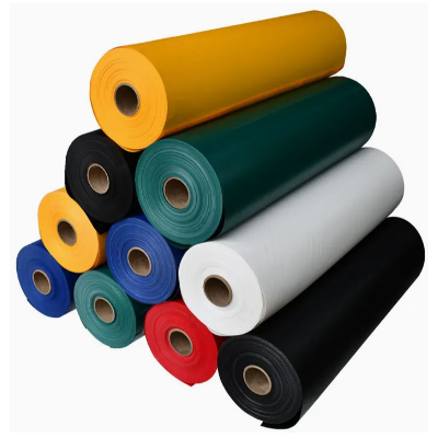
Match usable roll width to panel size and permitted rotation. Record direction identification with the roll and batch details.
Review the yarn axes alongside the actual strap, buckle, rail and seam arrangement. Local fixing details need their own validation.
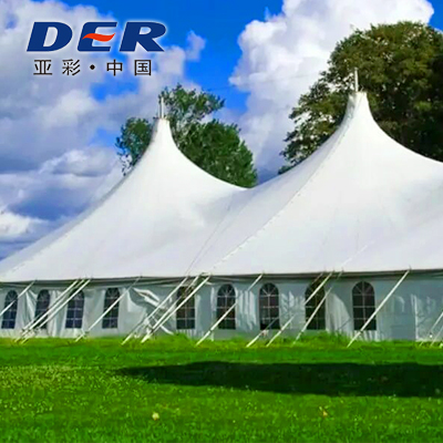
Follow the approved panel pattern and engineering requirements. Keep compensation, orientation and seam design connected.
Cost and supply questions: usable width, approved orientation, required grade, offcut restrictions, seam count and test scope can all affect a bulk quotation. Ask DERFLEX to confirm MOQ, sample availability and lead time for the selected construction and quantity.
Finished dimensions describe geometry. Add an explicit yarn-direction arrow so the converter knows which material axis belongs on each side.
Review both axes against performance requirements before accepting a yield improvement. Include face finish, printing and panel matching in the rotation rule.
Check reinforcement, coating, directional results and usable width. The same mass per area can describe different fabrics with different mechanical behavior.
Transfer the direction mark to every panel and retained offcut. A correct roll report cannot resolve an unlabeled mixed-panel assembly.
A dimensioned drawing helps DERFLEX discuss a suitable roll grade, panel layout and finishing route. If the orientation is not yet defined, describe how the cover is supported, tensioned and handled so the material review can start with the load path.
No. Directional strength depends on yarn selection, density, weave, coating interaction and processing. Compare both directions on the current technical data sheet using the same method, units and conditioning. Do not select a cutting direction from the word “warp” alone.
In a conventional full-width woven roll, warp normally follows the roll length and original selvage. Confirm this with the supplier if the material has been slit, rewound, cross-cut or assembled, or if the reinforcement is not woven. MD/CD labels should be tied to the actual yarn axes.
Yes, if the approved specification permits it and the exchanged yarn directions meet the required strength, extension and fit limits. Check seams, coated face, print orientation and panel matching as well. A lower material-use estimate alone is not sufficient approval.
Use the material axis whose verified performance meets the critical load and deformation requirements. Establish the load path from the support and attachment arrangement, then check the other axis and the complete assembly. The longest panel side does not necessarily carry the greatest tension.
Bias cutting may be part of a deliberate shaped-panel design, but off-axis behavior must be evaluated for that application. Diagonal loading can involve shear and yarn rotation. On-axis tensile results cannot simply be assigned to a bias panel, and tear behavior may follow a different trend.
Not necessarily. Equal denier describes yarn linear mass in the two directions. Yarn quality, count, weave crimp, coating and processing can still produce different finished-fabric results. Ask for both directional test values and their acceptance basis.
Include panel IDs, cut and finished dimensions, warp arrows, permitted rotation, face identification, seam and reinforcement details, tolerances, material code, required tests and an approved sample or drawing revision. Confirm quantity, destination, sample availability and lead time with DERFLEX.
Share your application, direction-marked drawing, material requirements, quantity and destination. Ask DERFLEX to review the material and fabrication details for your project.
Include its product code, direction marks and test report. Identify the fit or failure issue you want to resolve.