

News
Company News

ETFE Structure Material for Roofs, Facades & Cushions | DERFLEX

Update:2026/7/13 19:03:15 Views:
Architectural ETFE Film · Project Material Supply

ETFE Structure

Lightweight film material for transparent roofs, façades, skylights and pneumatic cushion envelopes.

DERFLEX supports architects, façade contractors, membrane fabricators, EPC teams and distributors with ETFE film direction, layer-by-layer thickness discussion, visual samples, printed-film communication, roll planning and export-ready supply. Final structural design, cushion fabrication, framing, inflation controls and code approval should be coordinated by the appointed specialists.

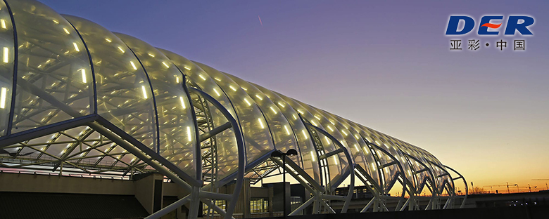
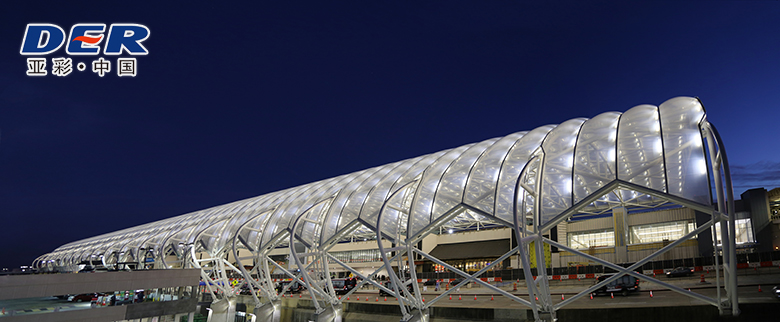
DERFLEX ETFE structure film in an illuminated architectural roof application
Product and project visual ETFE film works as part of a coordinated envelope, not as an isolated finished structure.
System Definition

What an ETFE Structure Actually Includes

An ETFE structure is a lightweight building-envelope system in which transparent or translucent ETFE foil is tensioned as a single skin or welded into air-supported cushions. The visible film is only one part of the assembly. The finished result also depends on panel geometry, seams, aluminium perimeter profiles, gaskets, drainage, supporting steel or cables, pressure control, installation tolerances and the local load strategy.

This distinction matters during purchasing. A request for “ETFE structure price per square metre” can refer to film only, fabricated panels, framed cushions, inflation equipment or a complete installed package. DERFLEX organizes the material discussion around the intended system so buyers can separate the foil-supply scope from specialist engineering and construction responsibilities.

Commercial clarity: Send the system concept, module sizes, layer count, appearance target, project location and required delivery scope. This provides a more useful basis for material selection than thickness or unit price alone.
Structural Directions

Three Common ETFE Structure Concepts

The right route depends on span, climate, transparency, thermal target, frame geometry, fabrication capability and maintenance strategy.

S

Single-Layer Tensioned ETFE

One foil layer is mechanically pre-tensioned and restrained by a frame, cable network or secondary support. The build-up is visually light and comparatively direct, while insulation, acoustics and deflection must be reviewed at system level.

  • Canopies, covered walkways and selected façades
  • Clear or printed film appearance
  • Requires pre-stress, edge and movement calculations
P

Pneumatic ETFE Cushion Structure

Two or more foil layers are welded around the perimeter and maintained at controlled low pressure. Cushion rise, layer count and print position can be coordinated to pursue daylight, shading and thermal objectives.

  • Large roof lights, atriums and venue envelopes
  • Two-, three- or specialist multi-layer assemblies
  • Includes air supply, monitoring and redundancy planning
H

Cable-Supported or Hybrid Envelope

Cables, steel grids or aluminium members control larger foil fields and complex geometry. The structure may combine stressed foil, cushions and rigid envelope interfaces within one architectural system.

  • Free-form roofs and façade features
  • Useful where module rhythm follows a complex frame
  • Needs coordinated load paths and installation sequence
Cushion Anatomy

Performance Comes from the Complete Assembly

A multi-layer ETFE cushion is not created by stacking film alone. The system must keep its shape under changing wind, rain, snow and temperature conditions while managing water, air pressure, movement and interfaces with the primary structure.

This schematic supports early purchasing communication only. The responsible engineer and system fabricator should confirm actual foil thicknesses, welds, cushion rise, aluminium profiles, gaskets, air settings and drainage details.
1
Outer ETFE FoilWeather face; clear, tinted or printed direction
Exterior
2
Pressurized Air ChamberMaintains form and assists load distribution
Pneumatic Zone
3
Optional Intermediate FoilCan support shading or thermal strategy
3–4 Layer
4
Inner ETFE FoilInterior face and light-diffusion layer
Interior
5
Aluminium Clamp, Seals and DrainageConnects the cushion to the supporting structure
Interface
Design Value

Why Project Teams Consider ETFE Structures

ETFE is most relevant when transparency, low envelope weight and architectural form are central to the brief. Final performance remains project- and system-dependent.

01 · Daylight

Bright Interior Environments

Clear foil can provide high visible-light transmission, while printed, tinted or layered directions can be discussed to manage glare and solar exposure.

02 · Weight

Reduced Envelope Dead Load

The low mass of foil panels can support lighter roof and façade concepts than many rigid glazing solutions, subject to the engineer’s complete structural design.

03 · Form

Curved and Free-Form Geometry

Flexible film and pneumatic modules can follow expressive grids, long curves and non-standard envelope geometries that would be difficult to reproduce with rigid panels.

04 · Surface

Low Dirt-Adhesion Direction

ETFE has a smooth fluoropolymer surface that can reduce dirt retention. Access, drainage and cleaning plans should still reflect the project environment.

05 · Appearance

Printing, Tint and Lighting

Frit patterns, translucent effects and backlighting can contribute to solar control and nighttime identity after physical samples and mock-ups are approved.

06 · Modularity

Panel-Based Envelope Planning

Roof or façade fields can be divided into coordinated modules, helping teams plan fabrication, delivery, access and potential future panel replacement.

Transparent Architecture Requires Precise Interface Planning

Roof curvature, support spacing, foil stress, seams, perimeter clamping, movement joints and water paths influence the film specification. Early coordination protects both the architectural intent and the purchasing scope.

Application Planning

Where ETFE Structure Systems Are Commonly Evaluated

The material is used where the building envelope needs daylight, visual lightness and geometry-specific engineering.

SPORT

Stadiums and Arenas

Roof edges, concourses, façade bands and entrance zones can use ETFE to create a bright and recognizable venue envelope.

TRANSIT

Airports and Railway Hubs

Large skylights, covered links and terminal halls can combine weather protection with natural light and lightweight support concepts.

RETAIL

Commercial Atriums

Shopping centres, hotel courts and entertainment spaces can use clear or fritted cushions to shape daylight and the central public experience.

FACADE

Feature Building Envelopes

Single skins or cushion modules can create transparent, translucent, patterned or illuminated façades with a distinct visual rhythm.

NATURE

Botanical and Learning Spaces

Conservatories, exhibition gardens and education buildings may evaluate ETFE where daylight transmission and lightweight enclosure are important.

CIVIC

Cultural and Public Buildings

Museums, pavilions, libraries and covered plazas can use ETFE as a contemporary roof or façade element subject to local performance requirements.

Specification Framework

Define the Material Before Requesting a Quote

The table is an RFQ starting point, not a substitute for calculations, approved samples, assembly testing or destination-market review.

Product DirectionArchitectural ETFE film or foil for transparent and translucent roof, façade, skylight and cushion-envelope applications.
Material StructureExtruded ETFE fluoropolymer film without woven reinforcement. Installed performance depends on foil, welds, clamps, frames, air system and engineering.
Thickness Discussion100 μm, 150 μm, 200 μm and 250 μm are common early-stage project directions. Final thickness should follow stress calculations and the selected layer arrangement.
System TypesSingle-layer stressed skin, cable-supported foil, two-layer cushion, three-layer cushion or specialist multi-layer envelope.
AppearanceClear/natural, translucent, white direction, project tint, dot or frit print, patterned film or lighting-oriented concept, subject to feasibility and sample approval.
Design InputsPlan and section drawings, module sizes, span, support spacing, building height, orientation, design loads, drainage concept and maintenance access.
Fabrication InputsRoll width, panel nesting, welding equipment, seam trials, splice policy, print registration, handling limits and fabricator acceptance criteria.
Commercial InputsEstimated quantity, sample schedule, delivery sequence, packaging, labels, project documents, destination and target order stage.
DERFLEX SupportMaterial-direction review, thickness discussion, sample and visual communication, printed-film coordination where applicable, roll quotation, packing and export delivery planning.
Responsibility Matrix

Separate Film Supply from the Installed Structure

Clear responsibility boundaries help project teams compare quotations, manage risk and identify the specialists needed for the finished envelope.

DERFLEX Material Conversation

ETFE Film Supply Support

  • Film type and layer-by-layer thickness discussion
  • Clear, translucent, tint or print direction communication
  • Physical sample and visual-reference coordination
  • Roll width, core, length, splice and edge-condition review
  • Packaging, labeling and export documentation planning
  • Repeat-order references and agreed inspection points
Specialist Project Scope

Engineering and Installed System

  • Structural analysis, load combinations and foil stress
  • Cutting patterns, welding design and cushion fabrication
  • Aluminium profiles, gaskets and thermal interfaces
  • Air supply, pressure monitoring, controls and redundancy
  • Drainage, snow and rain management, movement joints
  • Installation, commissioning, code approval and maintenance plan
Early Material Comparison

ETFE Structure vs Glass, PTFE and PVC/PVDF

No material is universally suitable. The strongest specification follows the building objective, not a headline feature.

Decision FactorETFE StructureGlass SystemPTFE MembranePVC/PVDF Membrane
Primary visual directionClear, translucent, printed or illuminated lightweight envelopeRigid transparency and crisp glazed appearanceDiffused white permanent membrane expressionOpaque or translucent fabric with broad color options
Weight directionVery low film weight; complete system still requires engineered supportsHigher panel and framing dead loadLightweight reinforced membraneLightweight reinforced membrane
Typical design priorityDaylight, low weight and expressive geometryClear views, acoustic mass and conventional façade detailingLong-life tensile roofs and diffused lightCost balance, weldability, color and flexible fabrication
System coordinationFoil stress, welds, clamps, cushion air, drainage and controlsGlass make-up, anchors, mullions, seals and drainagePatterning, edge details, steel/cable system and tensioningPatterning, welding, reinforcement, fixing and surface finish
Strong candidate whenTransparency and low envelope mass define the architectureRigid high-clarity glazing performance is requiredPremium permanent tensile architecture is intendedCommercial tensile structures need practical cost and customization
DERFLEX Project Support

A Material Supplier That Starts with the Envelope Brief

DERFLEX focuses on B2B architectural-film supply and specification communication. The goal is not to present film thickness as a complete design answer, but to help professional buyers define the material package around the intended roof, façade or cushion system.

01

Project-Oriented Selection

Material discussion connects system type, layer count, appearance, fabrication route and destination requirements.

02

Sample and Visual Coordination

Clear, translucent, tinted or printed directions can be reviewed through samples and agreed visual references.

03

Roll and Fabrication Planning

Roll format, nesting, welding trials, splice rules and handling requirements can be discussed with the fabricator.

04

Export-Ready Supply Communication

Packaging, labeling, documents and phased delivery can be aligned with international project procurement.

05

Clear Scope Boundaries

Film supply is distinguished from system engineering, cushion fabrication, controls, installation and code approval.

FAQ

ETFE Structure Questions from Project Buyers

Practical answers for architects, contractors, membrane fabricators, developers and procurement teams.

Is an ETFE structure the same as an ETFE cushion system?

No. ETFE structure is a broad term covering single-layer stressed foil, cable-supported film, pneumatic cushions and hybrid roof or façade assemblies. An ETFE cushion is one system type made from two or more welded foil layers maintained at controlled low pressure.

What ETFE film thickness is used in architectural structures?

Early discussions commonly include 100, 150, 200 and 250 μm film. The final thickness for each layer depends on module dimensions, design loads, foil stress, cushion geometry, printing, fabrication and the calculations of the responsible engineer.

Can DERFLEX supply a complete installed ETFE structure?

DERFLEX focuses on ETFE material supply and project specification communication. A complete installed structure normally also requires specialist structural engineering, cutting and welding, aluminium profiles, air controls, drainage, installation, commissioning and local-code approval. The required scope should be defined in the inquiry.

Can ETFE structure film be printed, tinted or illuminated?

Printed frit patterns, translucent directions, project tints and lighting-oriented concepts can be discussed subject to production feasibility. Print coverage and layer position influence daylight, glare, solar performance and visual consistency, so physical samples and mock-ups are recommended.

Does every ETFE structure need an inflation system?

No. Pneumatic cushions require controlled air supply and monitoring. A single-layer stressed skin does not use cushion inflation, but it still needs designed pre-tension, edge clamping, support geometry, movement allowance and structural verification.

What should I send for an ETFE structure quotation?

Send the project type, location, drawings, module dimensions, intended system, layer count, early thickness direction, visual target, estimated quantity, fabrication location, required documents, delivery stage and whether the request covers film only or a wider package.

Turn the ETFE Concept into a Supply-Ready Brief

Share your system type, drawings, layer count, film appearance, quantity, fabrication route and destination. DERFLEX will review the material-supply direction and identify the information that still requires specialist engineering confirmation.

Product descriptions and specification ranges are provided for preliminary purchasing communication. Final film values, assembly performance, testing, compliance and project suitability must be confirmed in writing for the selected material, system and destination market.
Consulting Services
+86-021-54361792 / 54361798
Email
sales@derflex.com