It Is a System Result
The test loads the hardware together with the surrounding hem, webbing, corner patch and coated fabric. A premium metal eyelet cannot compensate for a weak load path.



Tarpaulin grommet pull-out strength is the force a finished eyelet zone can resist under a defined pull test before the hardware, hem, reinforcement or surrounding fabric reaches the specified failure condition. The number is useful only when the specimen construction and test setup are defined. For industrial PVC tarps, truck covers, equipment covers and OEM programs, buyers should qualify the complete load path—not the metal grommet alone—by specifying the tarp material, hem or webbing reinforcement, hardware, pull direction, test geometry, conditioning, acceptance criterion and observed failure mode.
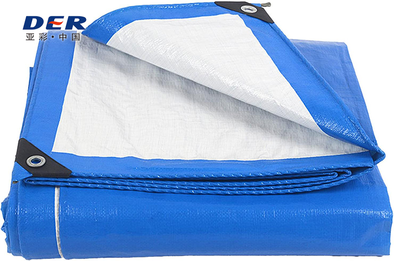
Grommet pull-out strength is a finished-product retention measurement, not a raw-fabric tensile value. It evaluates how much force a specific reinforced eyelet zone can withstand in a defined direction before an agreed failure condition occurs.
Because test fixtures, edge construction, reinforcement, specimen dimensions, grommet geometry and pull direction can change the result, there is no meaningful universal number that can be applied to every tarp. A procurement specification should define the method first, then state the required acceptance value.
The highest number is not automatically the best specification. First confirm that the test represents the way the finished tarp will actually be tied, hooked or tensioned.
The test loads the hardware together with the surrounding hem, webbing, corner patch and coated fabric. A premium metal eyelet cannot compensate for a weak load path.
A pull normal to the edge, diagonal pull and sideways peel can stress different yarns and reinforcement zones. The direction must be frozen in the test definition.
Grommet size, washer or toothed profile, hole preparation, setting pressure, hem depth, local patches and webbing architecture can all change retention behavior.
A single static pull test does not reproduce gusts, cyclic flap, vibration, abrasion or unequal load sharing across a full cover. Service design needs separate engineering judgment.
These values answer different questions. Tensile strength describes how a strip of material carries load; tear strength describes resistance to tear propagation from a cut or notch; grommet pull-out strength describes a concentrated hardware load in a finished edge construction. For the mechanical-property distinction, see DERFLEX’s tarpaulin tensile strength vs. tear strength guide.
A useful test is repeatable, representative and fully documented. It should reproduce the finished edge construction rather than punching a grommet into a convenient scrap of flat fabric.
| Test Variable | What Must Be Defined | Why It Matters |
|---|---|---|
| Specimen construction | Actual tarp material, hem layers, webbing/patches, seams or welds and production-set hardware | Flat material cannot represent a finished attachment zone. |
| Grommet location | Edge, corner or another defined hardware position | Corner geometry can concentrate force differently from a straight edge. |
| Pull direction | Normal to edge, diagonal or another application-specific direction | Different directions activate different yarns, seams and reinforcement paths. |
| Fixture / connector | Hook, pin, shackle, rope loop or defined test fixture | Connector diameter and contact shape can change local deformation. |
| Machine settings | Gauge/fixture arrangement and pull rate used by the agreed procedure | Results should only be compared when the setup is equivalent. |
| Conditioning | As-received, wet, cold, heat-aged or another agreed state when relevant | Material flexibility and coating behavior can change with condition. |
| Failure definition | First permanent damage, hardware release, fabric rupture or other agreed endpoint | Two labs can report different numbers if they stop the test at different events. |
| Report output | Peak force, units, failure mode, sample ID and construction ID | A number without traceable construction and failure evidence is difficult to use in procurement. |
Do not convert a single eyelet pull-out result directly into a wind rating, lifting capacity or allowable service load. Real covers experience load sharing, slack, gusts, vibration, impact, abrasion and repeated cycles. Where safety or structural performance matters, the complete installation and applicable engineering requirements should govern the design.
For a broader view of material, seam, hardware and QC checks, use the DERFLEX tarpaulin testing standards and buyer QC guide. It explains why finished hardware and reinforcement require their own pull or practical load checks when specified.
Two specimens can reach similar peak force and still reveal different design weaknesses. Failure location is often the fastest clue to which part of the load path needs to change.
| Observed Failure | What to Review | Possible Design Direction |
|---|---|---|
| Metal eyelet remains intact but material pulls out | Hem thickness, patch/webbing, grommet washer/profile, edge distance and pull angle | Spread the load through a wider reinforced zone rather than only changing the eyelet metal. |
| Diagonal tear starts at grommet | Anchor alignment, tie-down angle and yarn direction around the opening | Realign the pull, add local reinforcement or change the attachment architecture. |
| Multiple adjacent grommets distort | Spacing, uneven tension and whether all fixing points are engaged | Review load sharing and installation sequence, not only individual point strength. |
| Corner fails before straight edge | Corner geometry, folded layers and multi-directional tension | Use a dedicated corner construction or larger patch matched to the actual force path. |
| Repeated field failures but lab peak looks acceptable | Cyclic wind, abrasion, connector wear, folding and environmental conditioning | Add a durability or conditioned-sample check instead of relying on one new-sample static test. |
If your main question is failure diagnosis rather than laboratory qualification, use the DERFLEX guide on why tarps rip around grommets. This page stays focused on measurement, reinforcement qualification and purchasing specifications.
Reinforcement works by moving force away from a small eyelet opening and into a wider section of the tarp. The correct architecture depends on the pull direction, handling cycle and surrounding material—not on a universal reinforcement percentage.
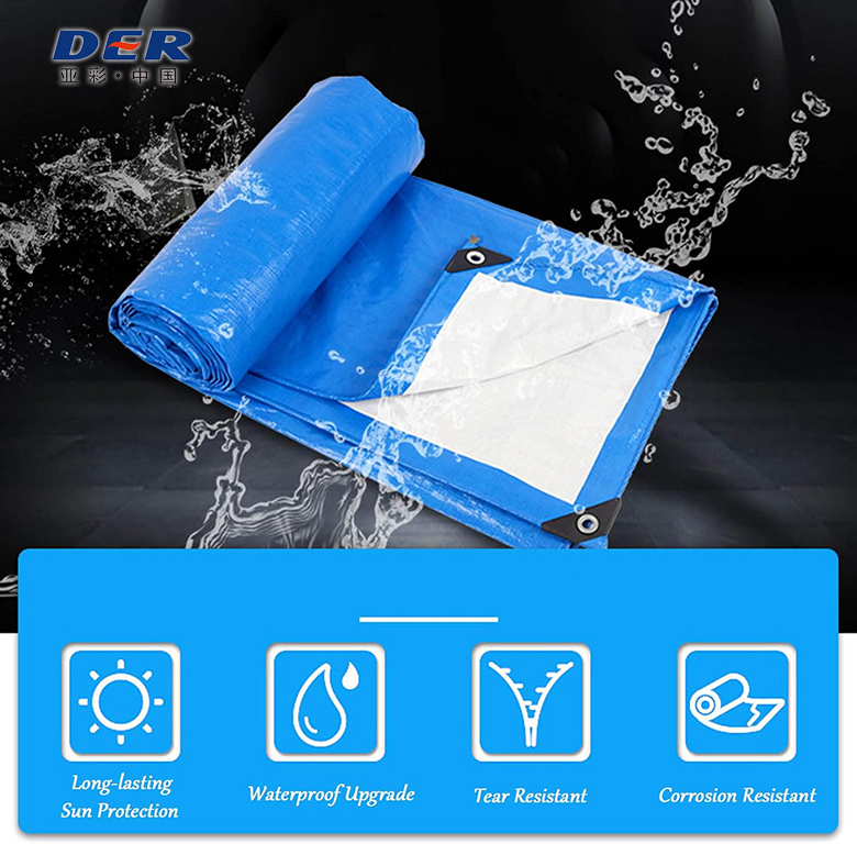
Adds local thickness and moves the eyelet away from a single raw edge. Suitable as a base construction when the duty cycle is moderate and the test confirms the requirement.
Extends the reinforced material zone around the hardware. Layer geometry and bond/seam quality should remain consistent in production.
Can spread tie-down force along a longer portion of the perimeter. Webbing width, overlap and attachment method should be part of the approved construction.
Useful where selected eyelets carry higher loads or where existing field evidence identifies a repeat failure zone.
Corners often see multi-directional pull. A larger engineered patch can spread load beyond the eyelet and into the adjacent perimeter.
For repeated directional pull, a D-ring sewn or welded into a wider reinforced tab may be more appropriate than asking one eyelet to carry the entire load.
For edge architecture options beyond the local grommet zone, see tarp edge reinforcement methods. If the application needs a different attachment architecture, compare custom tarps with D-rings.
Start with the real load pattern. Then select the hardware and reinforcement system that can be sampled, tested and repeated in production.
| Application | Typical Load Pattern to Review | Reinforcement Direction | Qualification Focus |
|---|---|---|---|
| Outdoor storage cover | Perimeter tie-down plus intermittent wind uplift | Continuous reinforced hem; corner reinforcement where anchors pull harder | Representative edge and corner pull tests; installation plan that avoids loose panels. |
| Construction / temporary enclosure | Wind cycling, repeated installation and variable anchor geometry | Wider load distribution around frequent fixing points | Pull direction, spacing, conditioned samples where climate is severe, and visual inspection after repeated use. |
| Truck / trailer cover | Dynamic wind, vibration, folding, abrasion and repeated tension | Webbing-reinforced perimeter, dedicated high-load points, wear zones and appropriate hardware | Finished-sample hardware retention plus fit, load sharing and abrasion review. |
| Equipment cover | Localized tie-down around a stable geometry | Reinforcement aligned with known anchor points | Drawing-based hardware positions and repeatable pull direction. |
| Large industrial enclosure | Large panel area with unequal perimeter loads | Engineered attachment pattern; grommets may be combined with D-rings, webbing or other fixing systems | Application-specific engineering; do not infer whole-cover capacity from one eyelet test. |
| OEM repeat program | Consistent use pattern across production lots | Frozen construction drawing and approved sample | Defined test method, sampling plan, traceable material/hardware code and failure-mode reporting. |
It can improve load sharing across the finished tarp, but it does not automatically increase the retention strength of one individual eyelet. The benefit only appears when multiple fixing points are actually engaged and the surrounding reinforced edge is capable of transferring load between them. For spacing, hardware and customization options, see DERFLEX custom tarps with grommets.
This example is illustrative—not a claimed customer case. It shows how failure-mode evidence can guide a more useful reinforcement change than simply selecting a heavier tarp.
For transport programs where vibration, wind and repeated tie-down are part of the load cycle, compare the attachment design with DERFLEX truck tarp manufacturing and reinforcement options.
Not necessarily in the finished tarp. Hardware material influences corrosion behavior, deformation, wear and compatibility, but grommet pull-out is often governed by the complete reinforced edge and installation geometry.
Review corrosion exposure, connector shape, appearance, market requirement and the setting equipment used in production. The eyelet and washer should be compatible with the tarp thickness and reinforcement stack.
Do not accept “brass,” “stainless” or “heavy duty” as a substitute for a tested finished construction.
If retention strength matters, test the actual material + hem + patch/webbing + grommet combination. Record both peak force and where the assembly failed so engineering changes target the real weak point.
A stronger eyelet can simply move the failure into the surrounding fabric if the load path is not reinforced.
The most useful RFQ language freezes the construction and the test together. Avoid asking suppliers for a pull-out number without defining what that number must represent.
“Finished grommet zones shall match approved construction drawing [ID]. Pull-out testing shall use the agreed specimen, fixture, pull direction and conditioning. Record peak force and failure mode. Minimum acceptance: [buyer-defined value] under the specified method. Any change to fabric, hem, webbing, grommet or setting process requires re-approval.”
It converts an ambiguous marketing phrase into a repeatable acceptance requirement. Procurement can compare approved samples and production lots using the same, construction, method and failure definition.
For OEM and industrial tarp programs, the commercial value is not a one-time test number. The useful outcome is a controlled construction that can be sampled, approved, repeated and inspected by lot.
For fleets and transport-focused OEM supply, this same specification logic can be carried into DERFLEX heavy-duty PVC truck tarp programs.
Both routes can be appropriate, but they solve different problems. Buyers who need a repeatable pull-out requirement should purchase a defined construction, not only a product label.
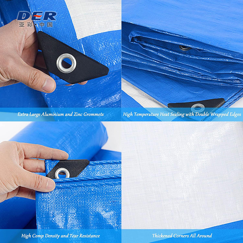
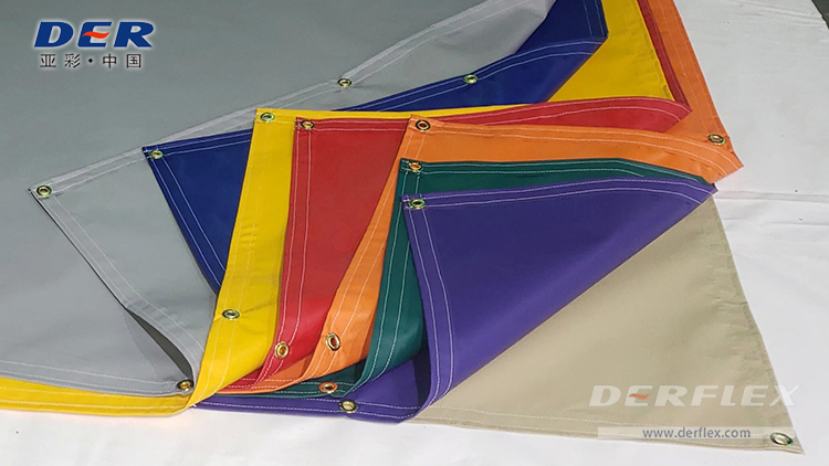
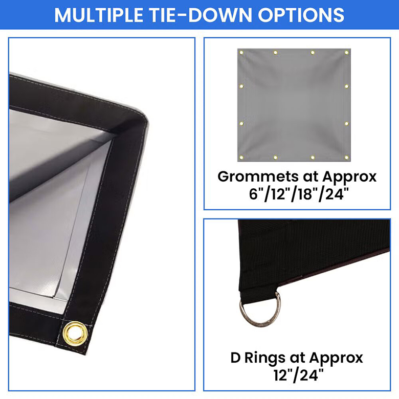
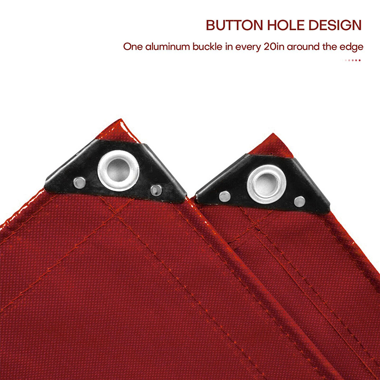
Composite detail boards are shown at large size so the grommet, hem and corner construction remain readable. Supporting product images use separate, non-duplicated site assets.
A complete brief helps DERFLEX recommend a construction and prepare the right sample or drawing without assuming unsupported performance values.
There is no single minimum that fits every tarp. The required retention strength should be based on the application, attachment layout and a defined test method. The specification should state the specimen construction, pull direction, fixture, failure endpoint and buyer-defined acceptance value.
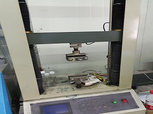
A representative finished grommet zone is secured in a defined fixture and pulled in a specified direction using a controlled mechanical test. The report should identify the complete construction, test setup, units, peak force and failure mode. Edge and corner specimens may need separate qualification.
Not for every tarp construction and application. Buyers may use a company method, project method or an agreed procedure. The critical point is to freeze the method and construction so approved samples and production lots are compared consistently.
Metal type alone does not determine finished pull-out strength. Brass, stainless steel and aluminum differ in corrosion behavior, stiffness, wear and compatibility, while retention also depends on grommet geometry, setting quality, hem layers, reinforcement and pull direction.
No. Higher GSM or thickness may change the local material stack, but the attachment zone can still be weak if the hem, webbing, patch, grommet setting or load direction is poorly matched. The finished reinforced zone should be tested as an assembly.
Closer spacing can provide more load-sharing points when they are all used, but it does not automatically increase the strength of each individual grommet. The reinforced perimeter and installation method must distribute load effectively.
D-rings can be useful for repeated, directional or higher-load tie-downs because webbing tabs and backing patches can transfer force into a wider area. The ring orientation, webbing overlap and attachment process still need to match the real pull direction.
Include the sample and material ID, hem/reinforcement construction, grommet specification, hardware position, specimen geometry, pull direction, fixture, conditioning, test settings, peak force, units, failure mode and acceptance decision. Photos of the failed specimen can make comparisons much clearer.
Send DERFLEX your application, finished dimensions, hardware map, reinforcement concept, tie-down direction and acceptance method. The team can discuss a custom PVC tarpaulin construction and sample plan for your OEM, distributor or industrial project.